| Click On Image For Full Size Image |
Size | Image Description | Contributed By And/Or Copyright |
|
|---|---|---|---|---|
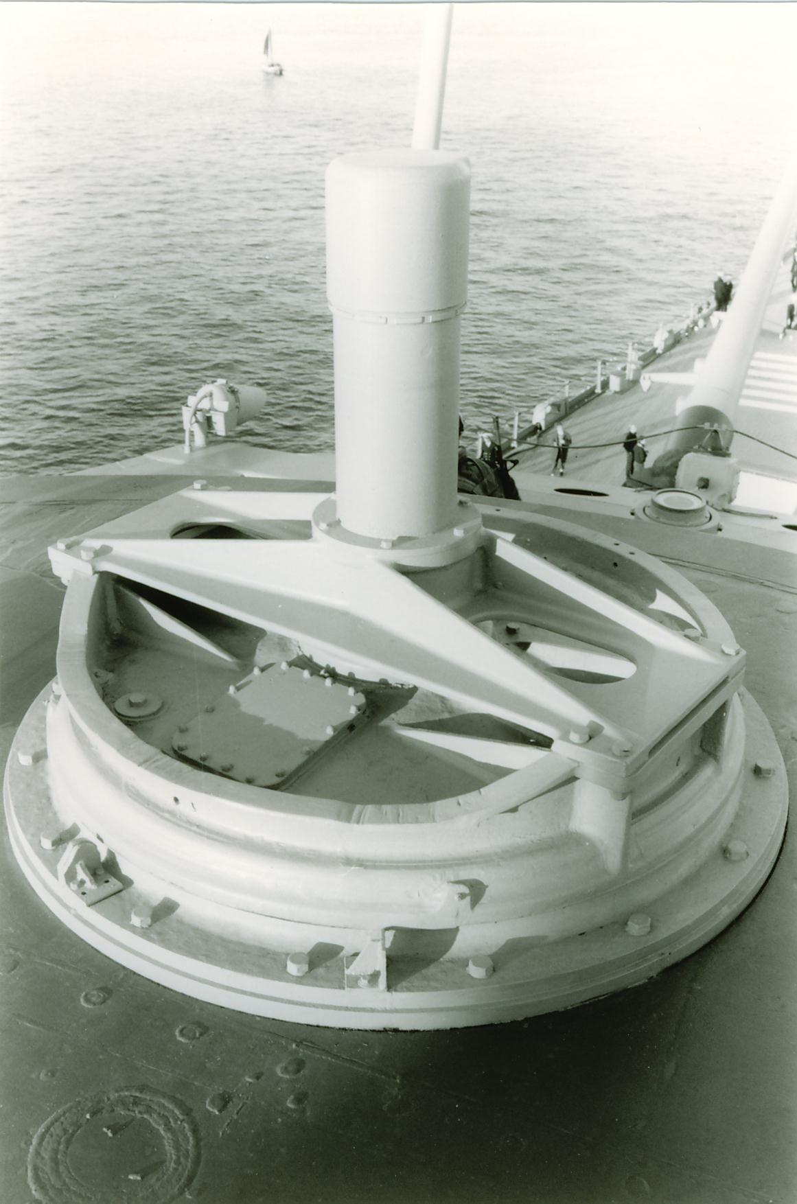 |
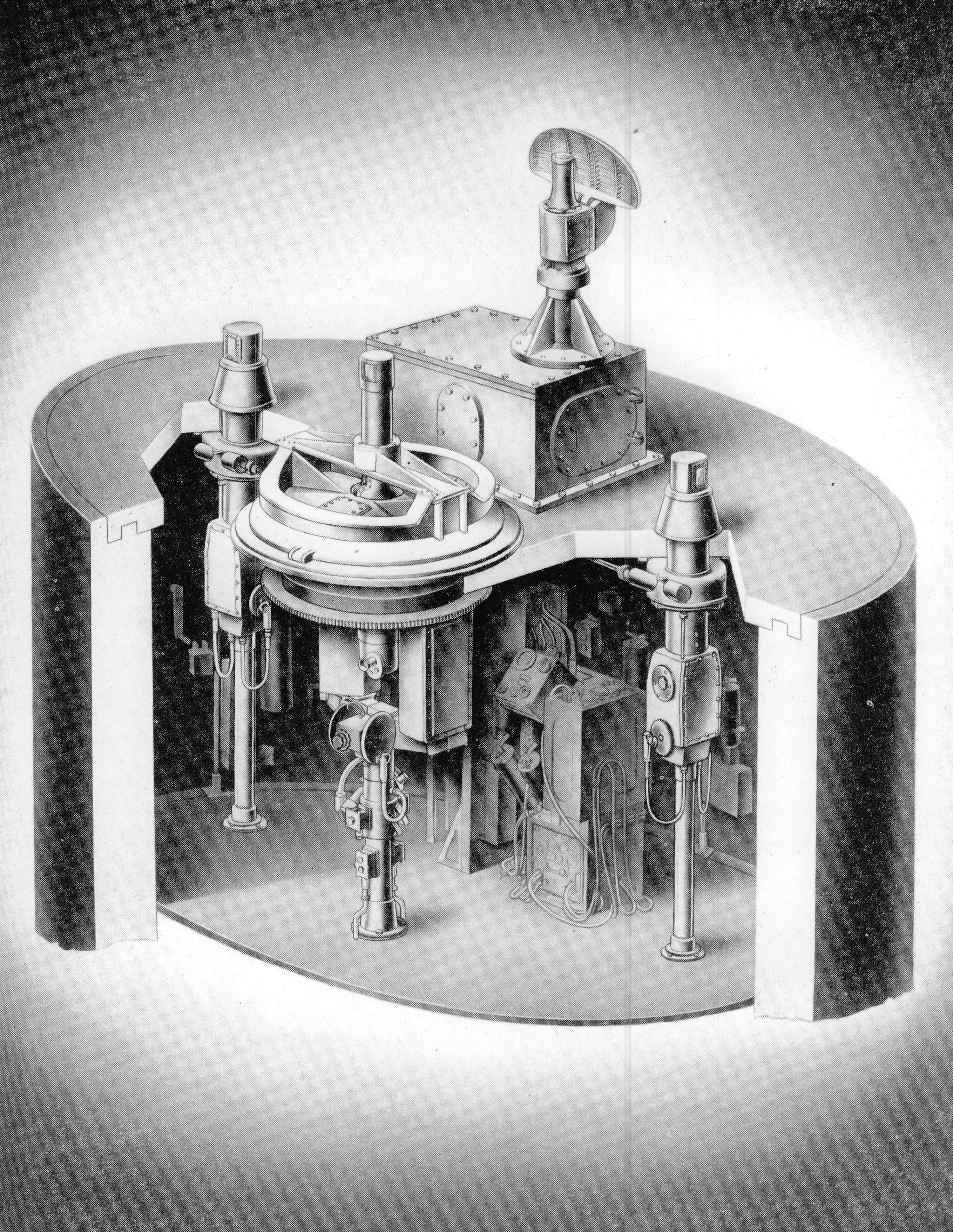
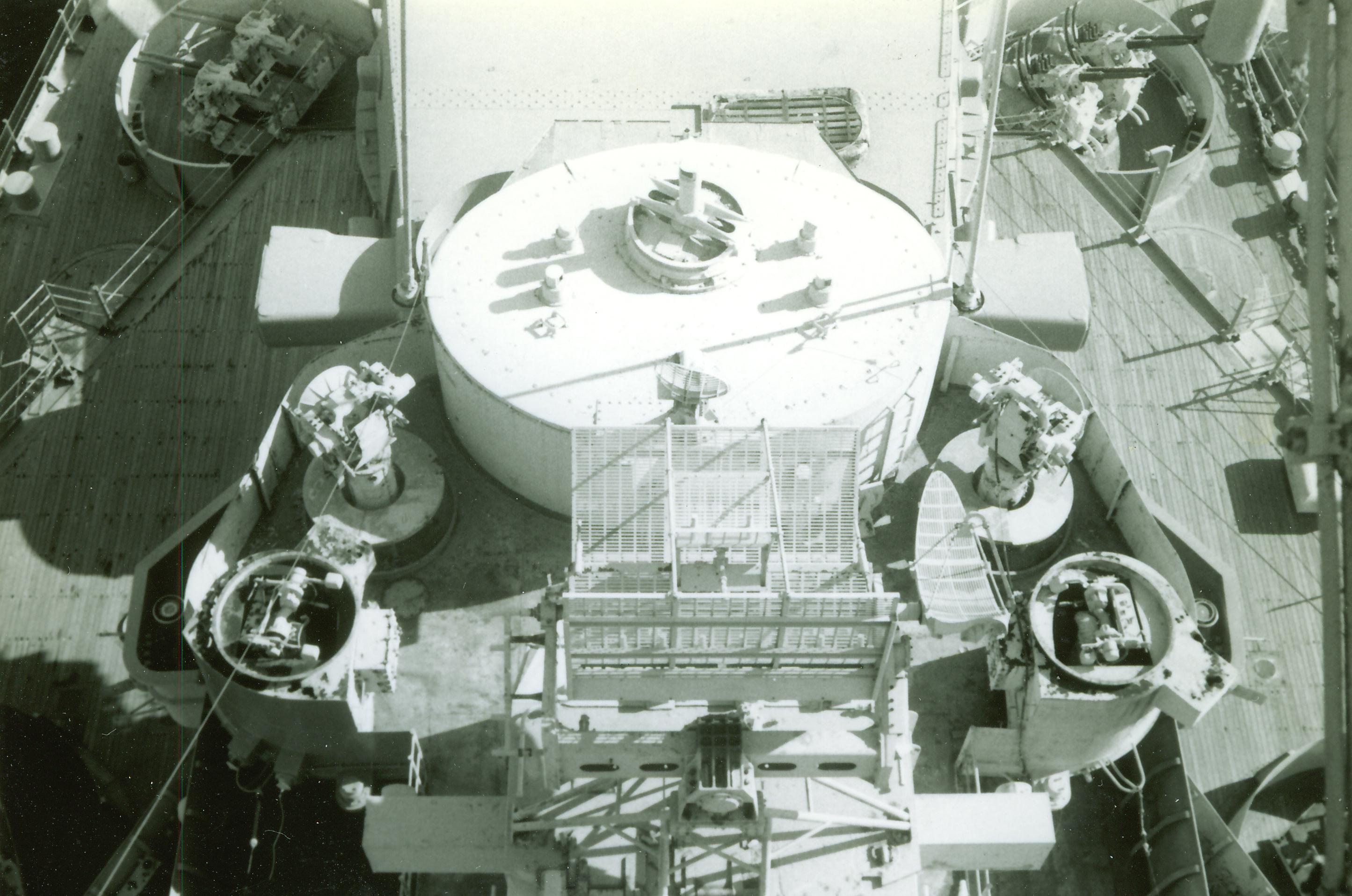
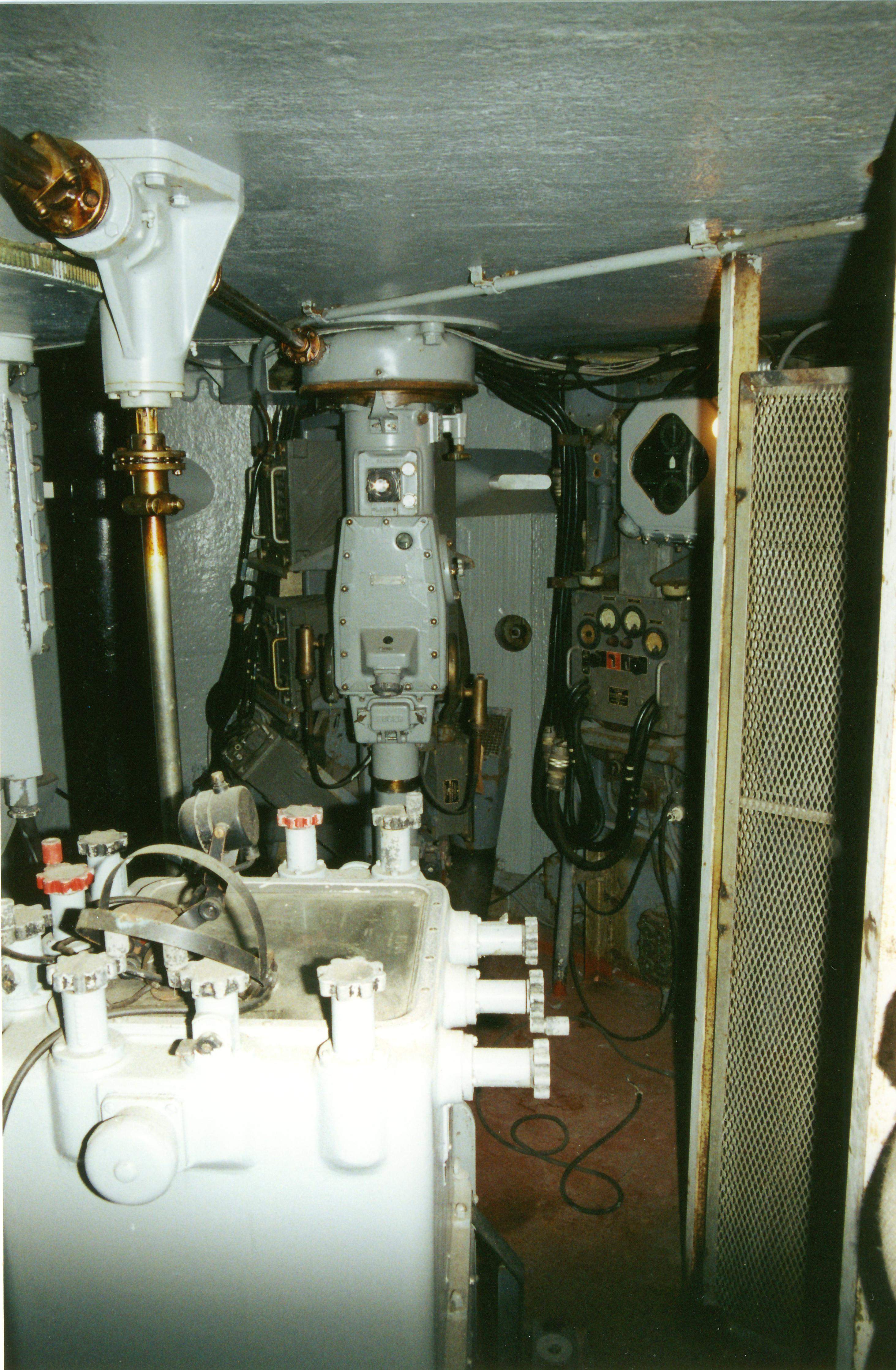
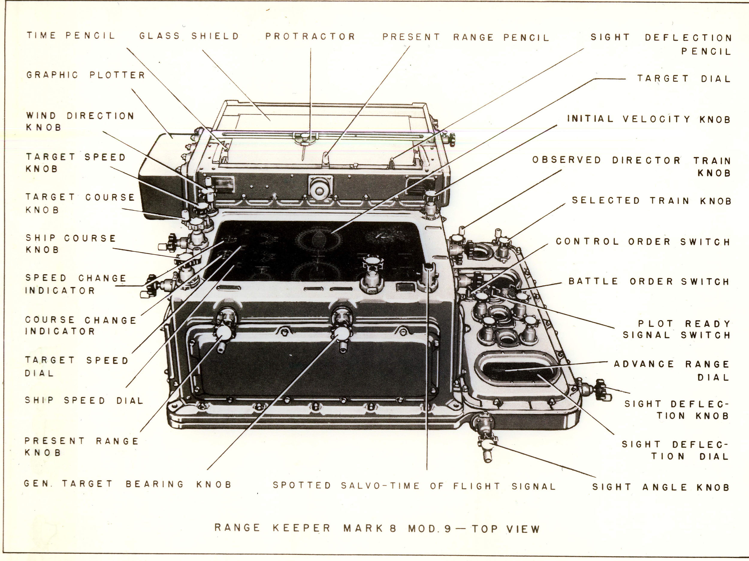
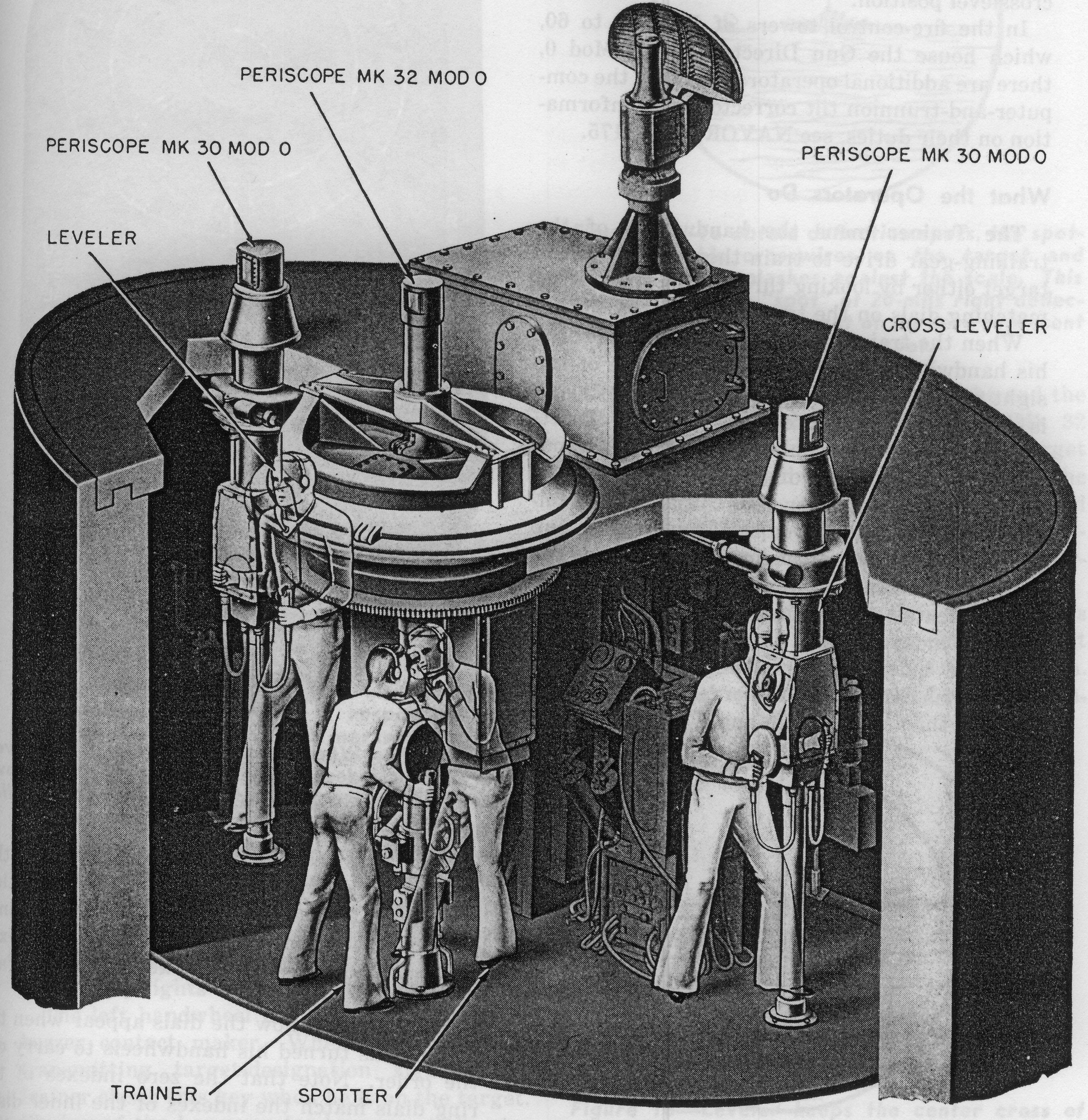
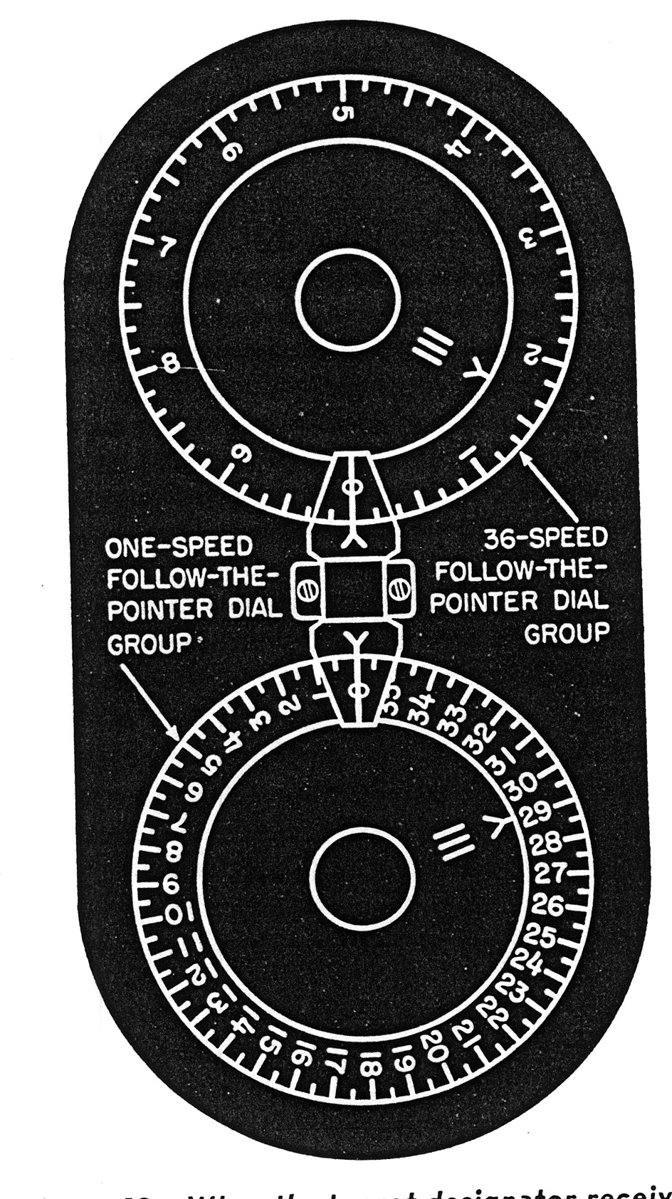
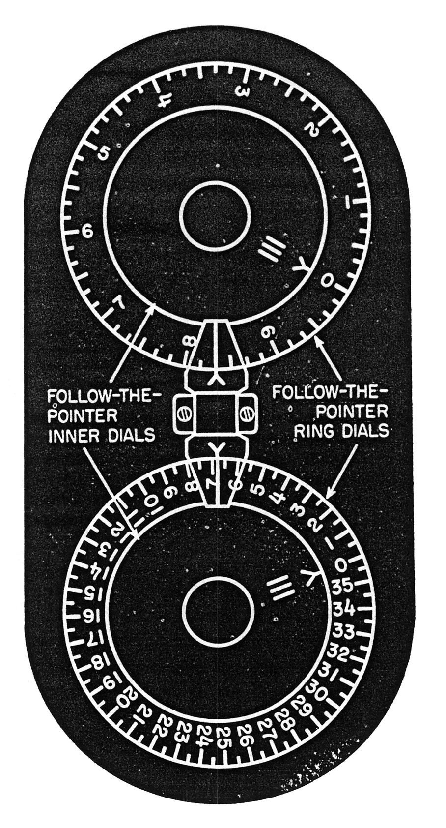
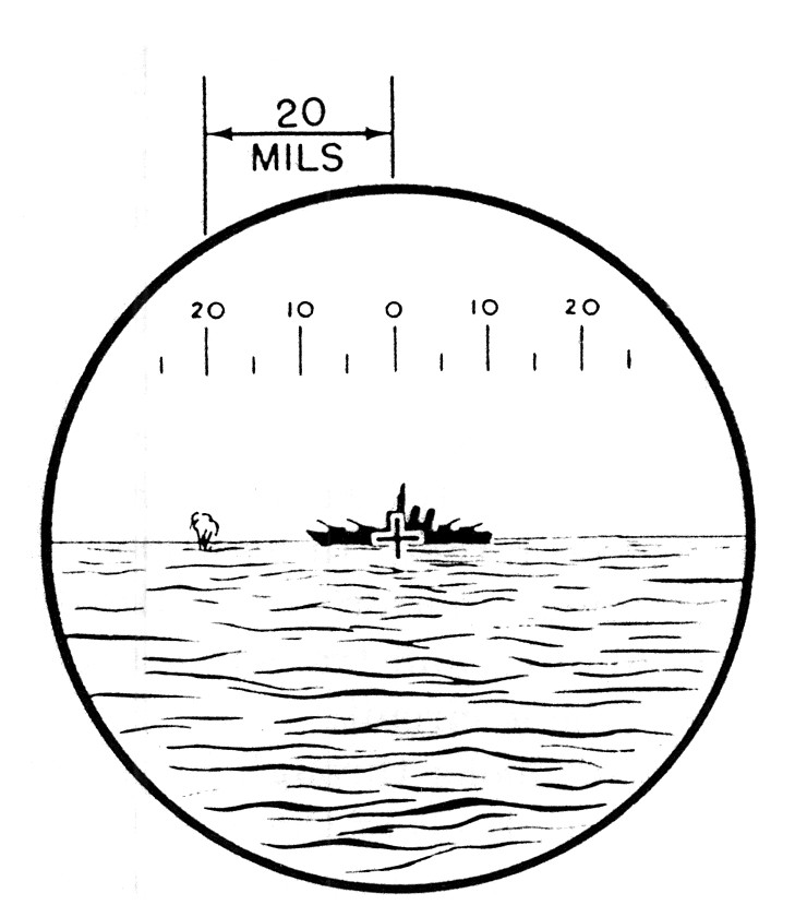
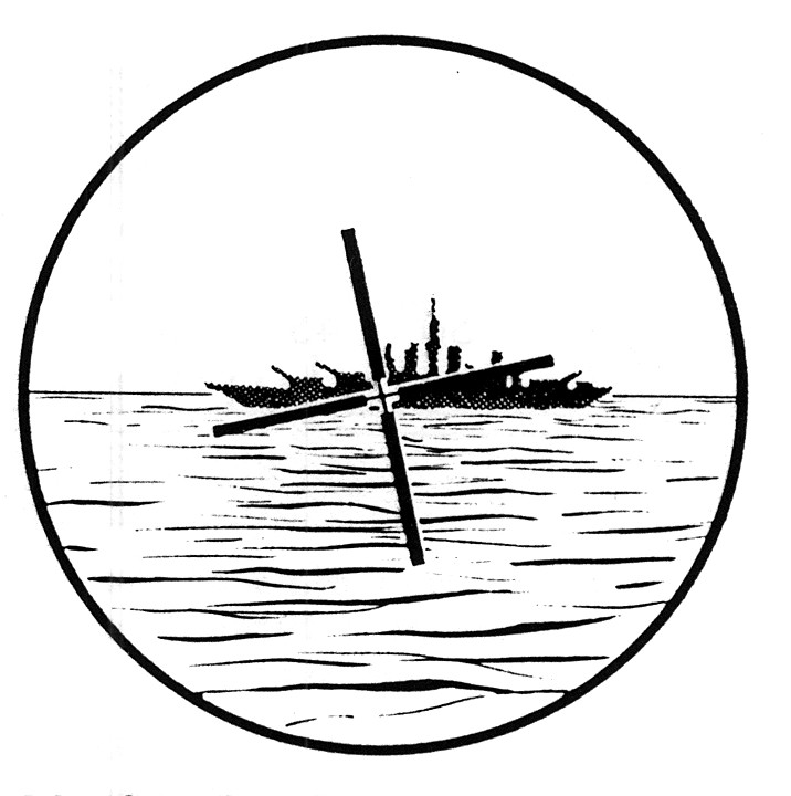
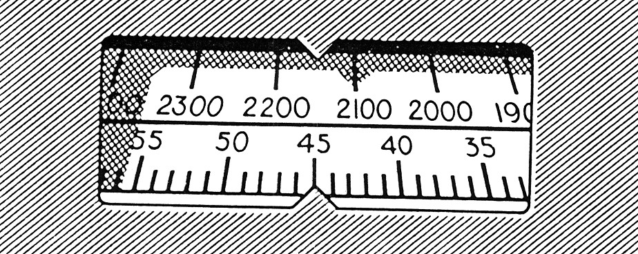
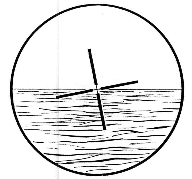
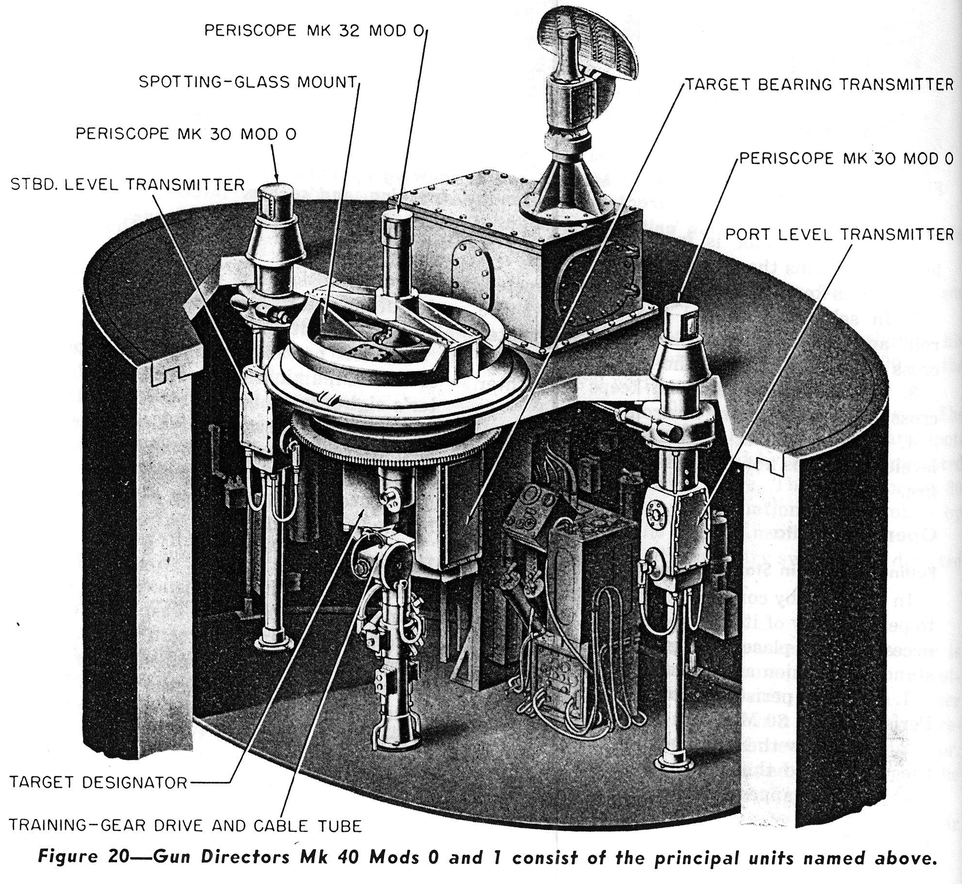
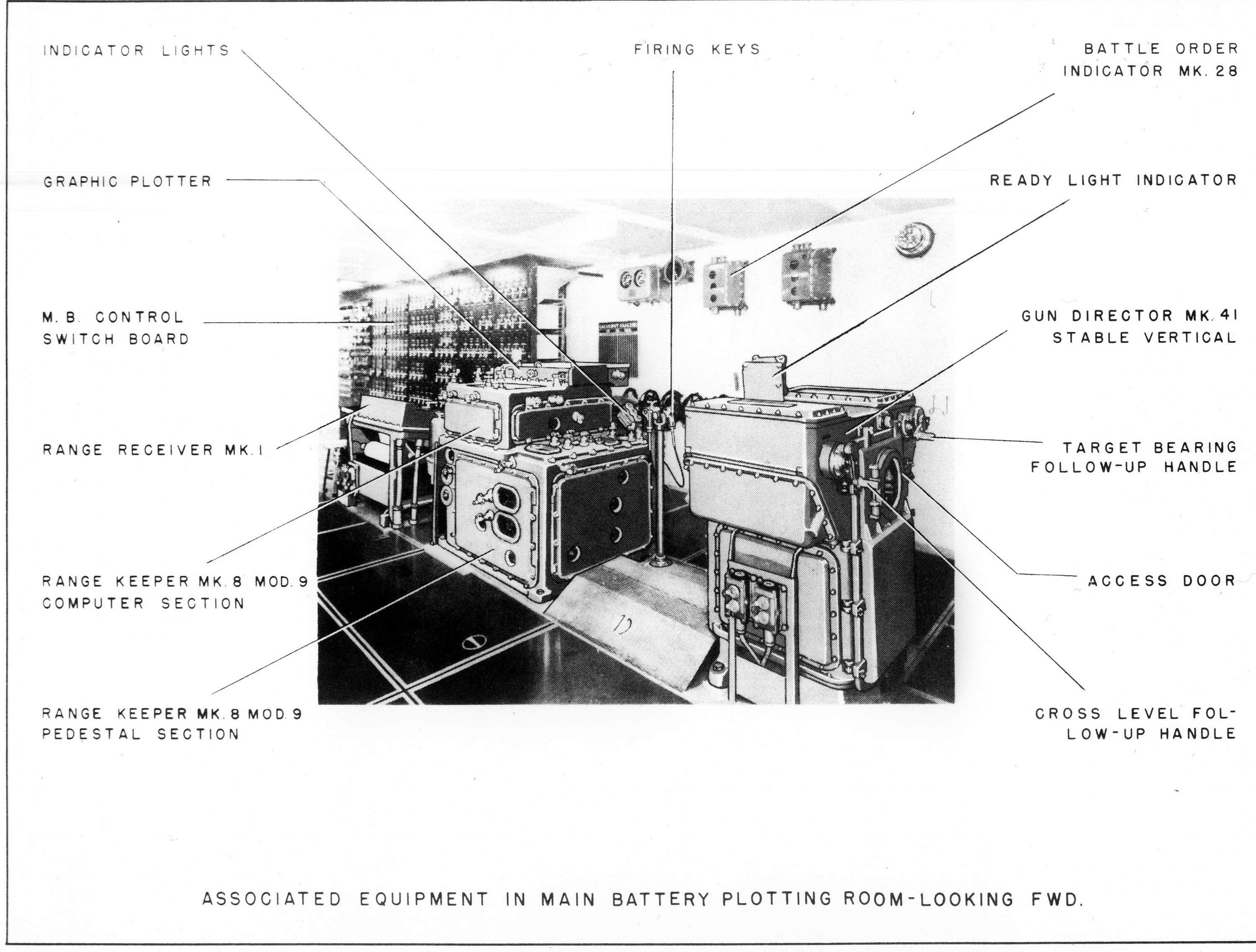
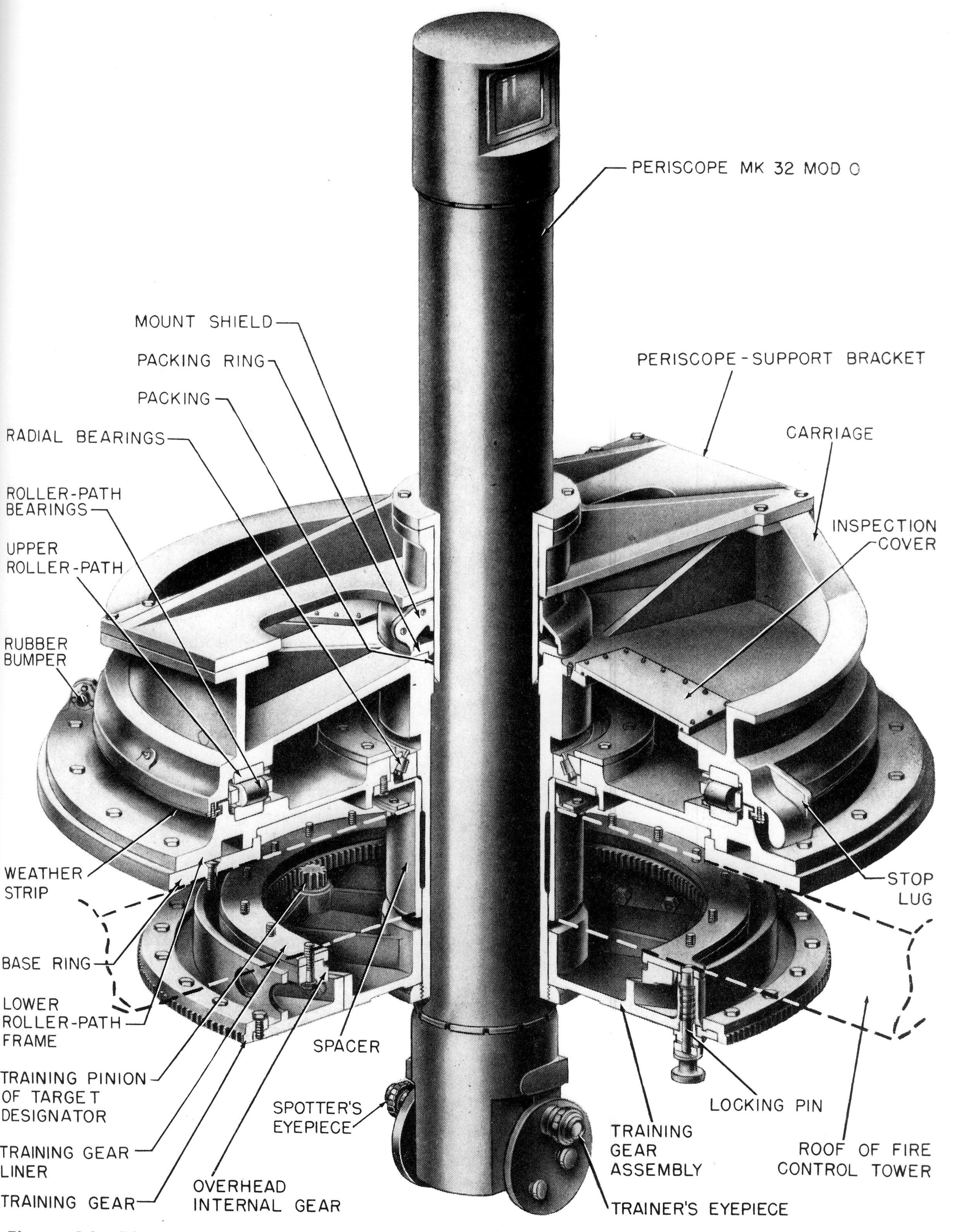
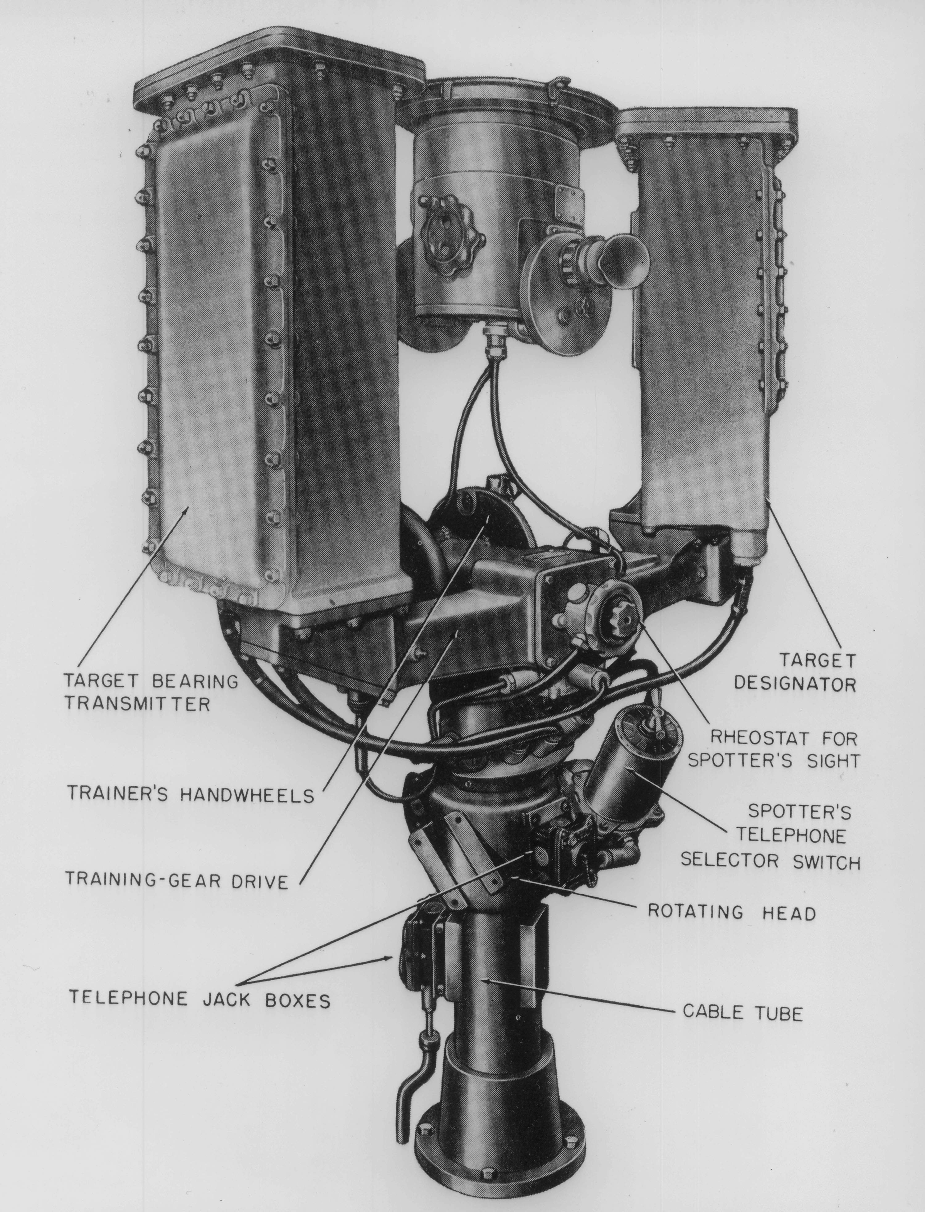
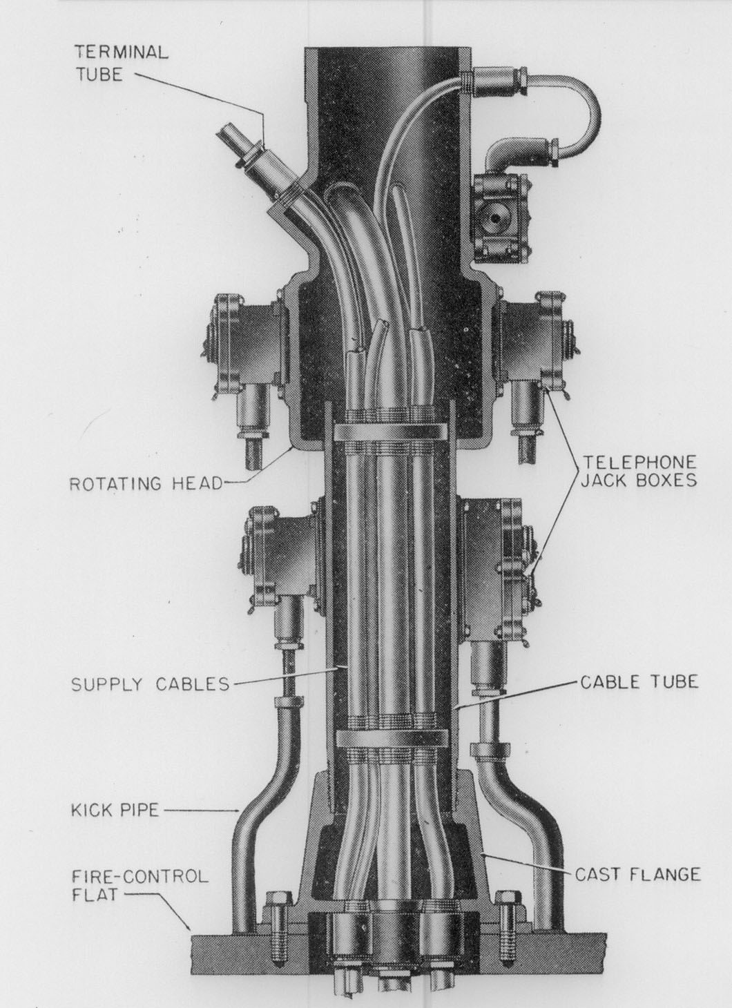
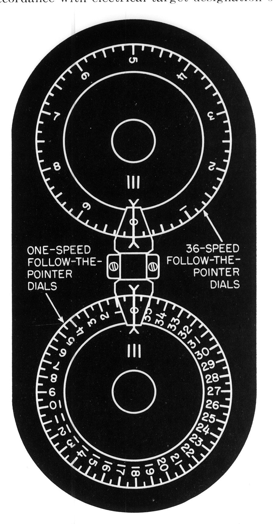
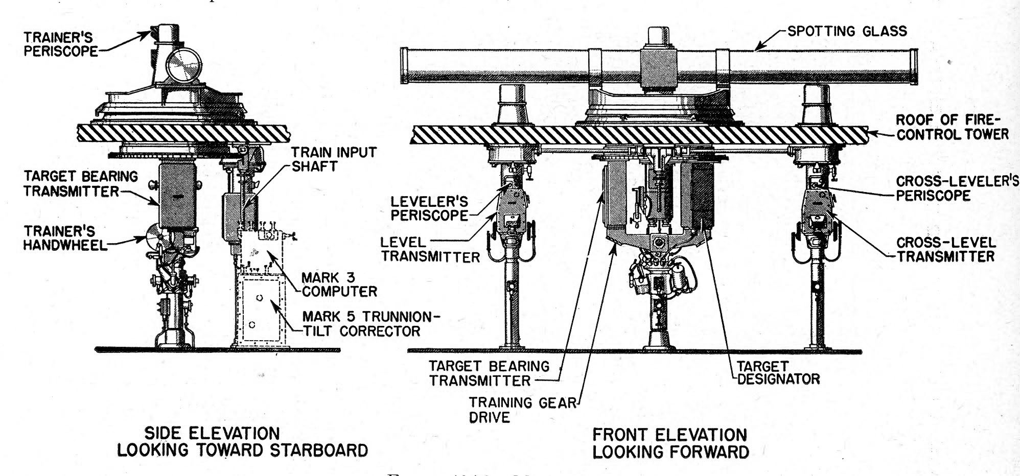
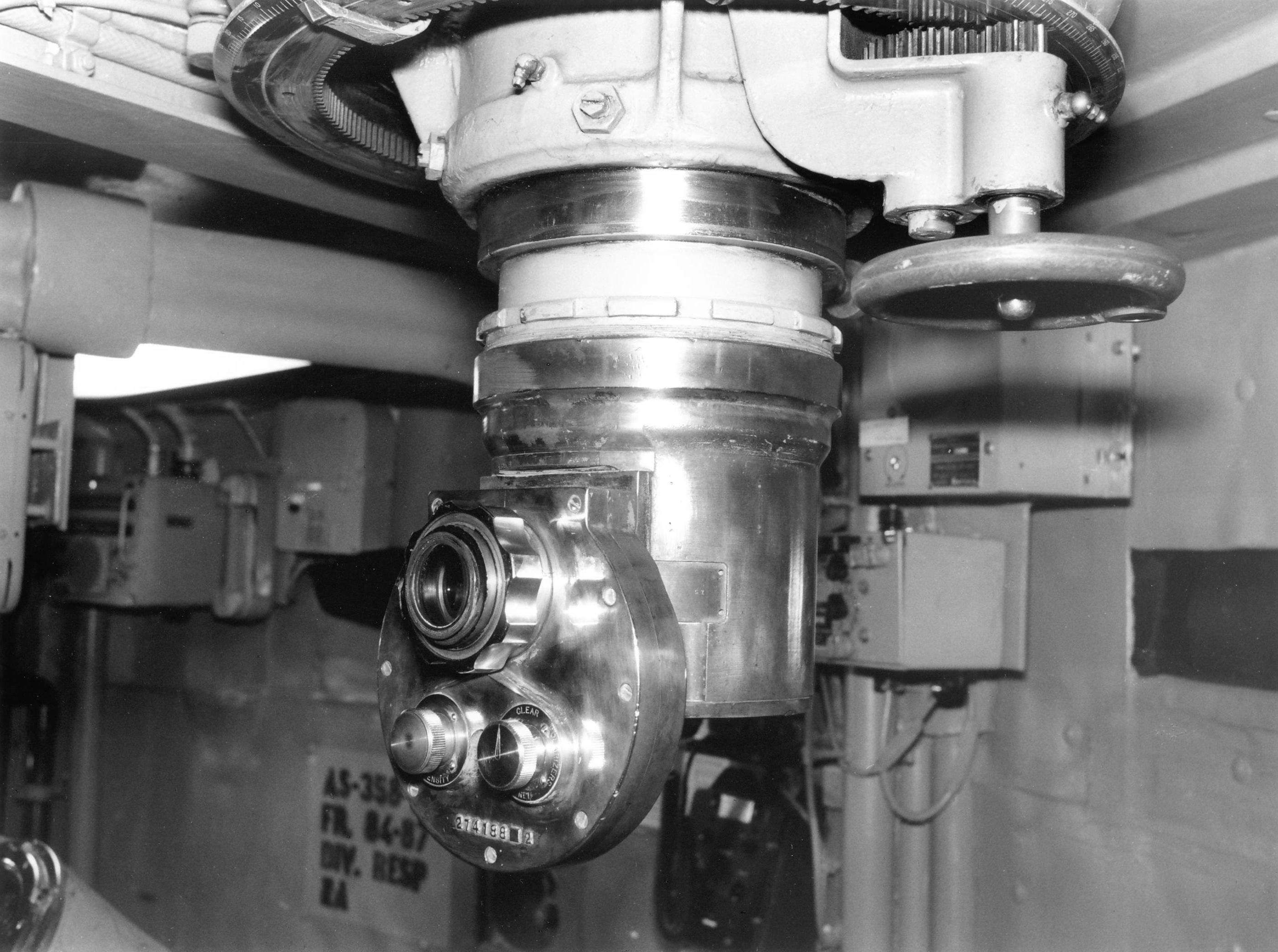
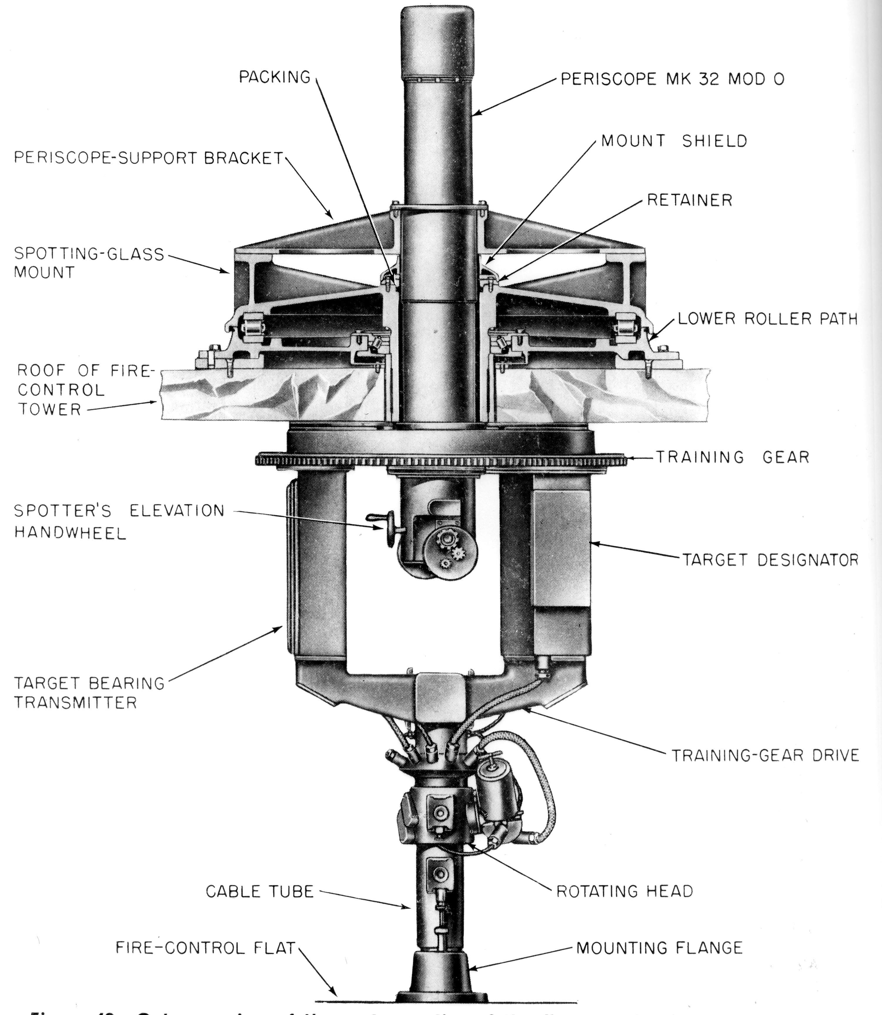
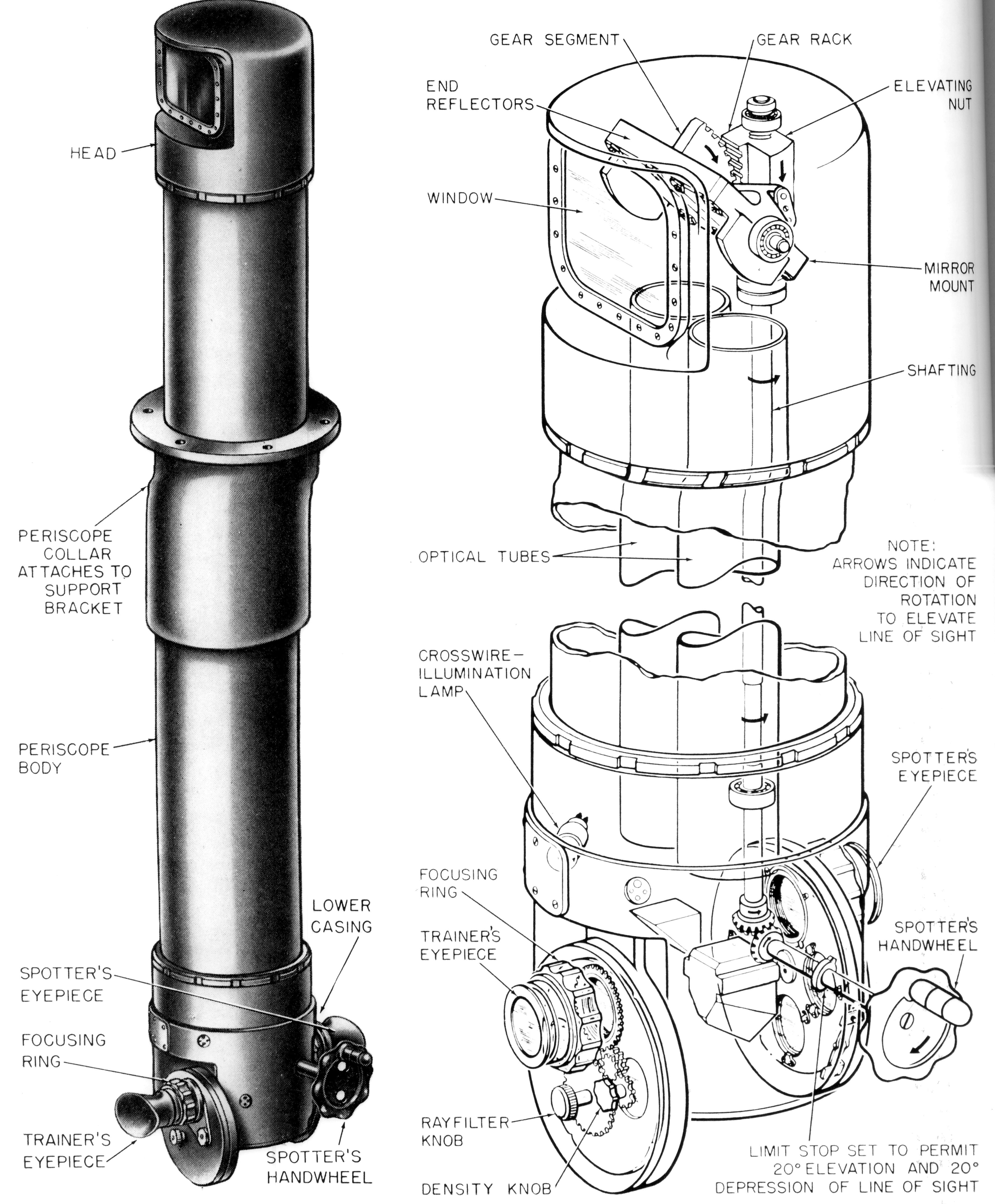
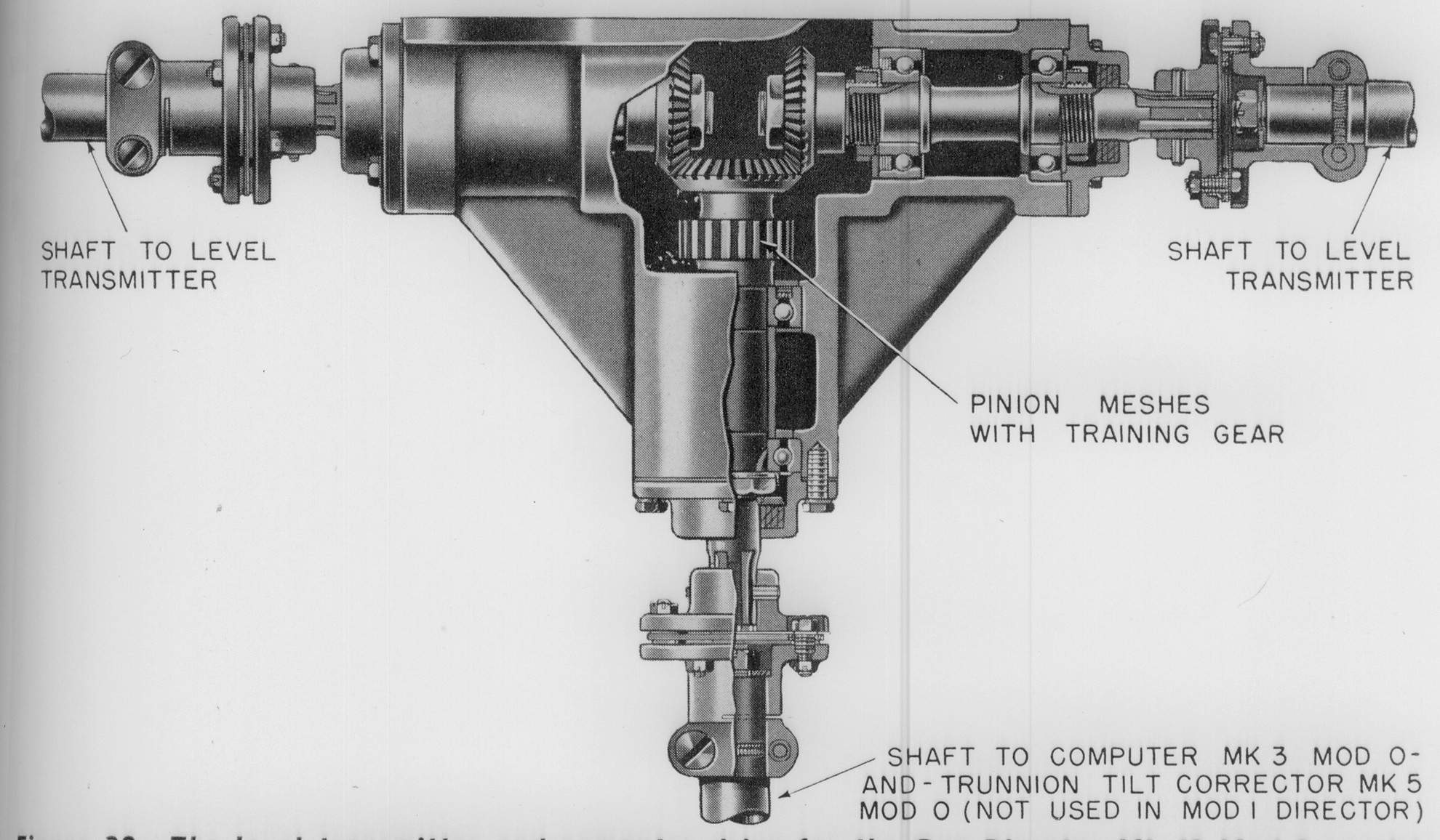
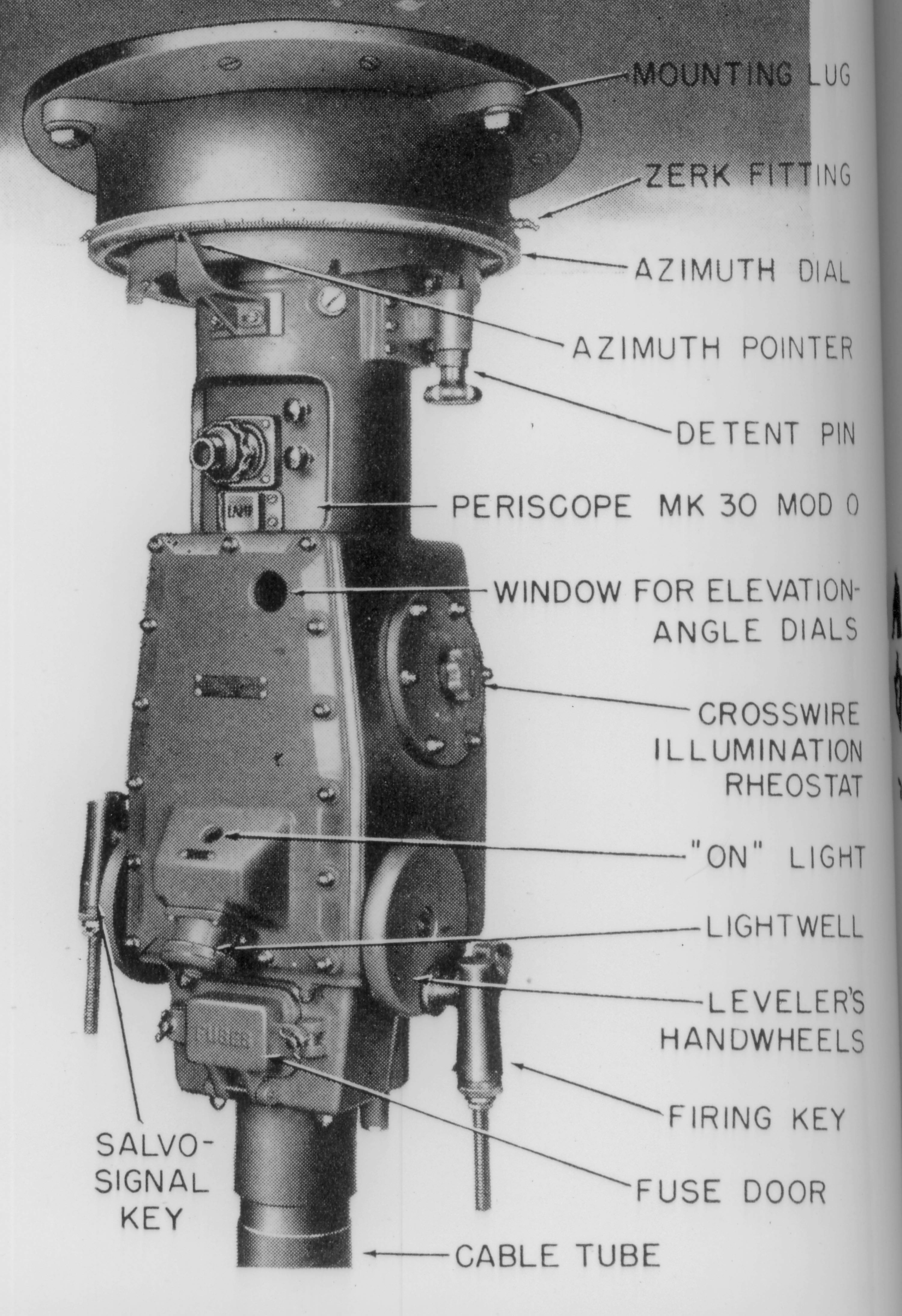
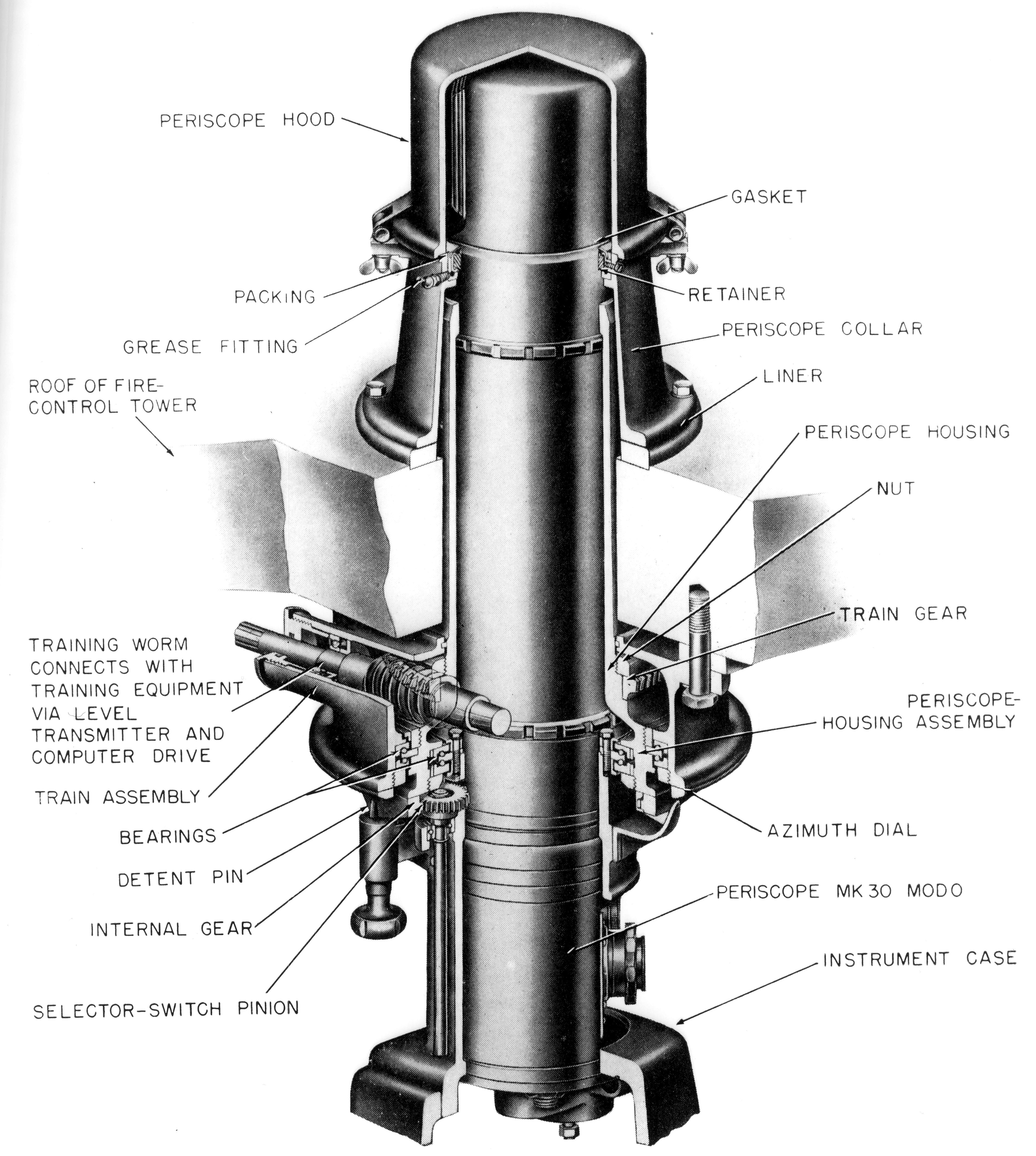
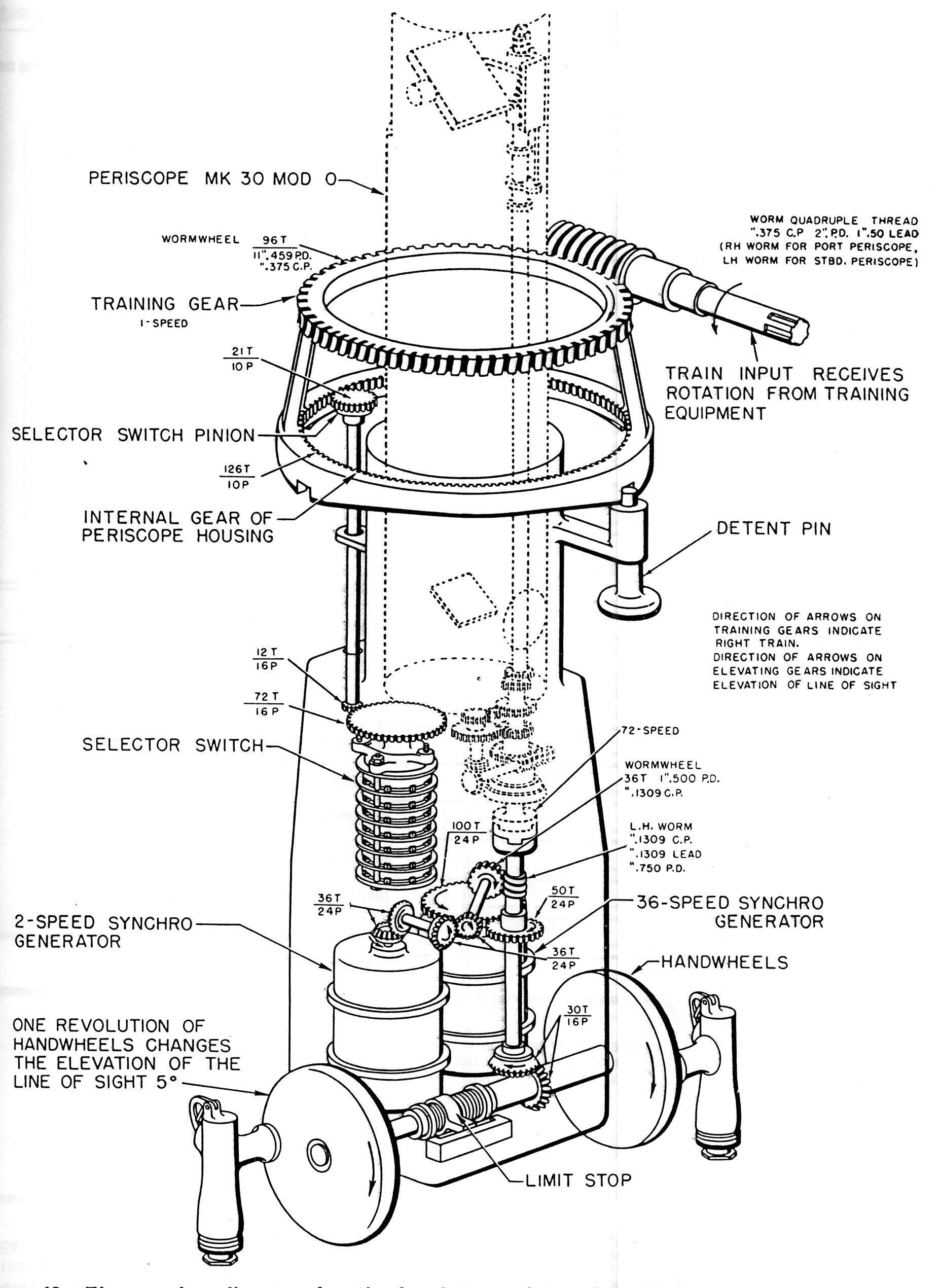
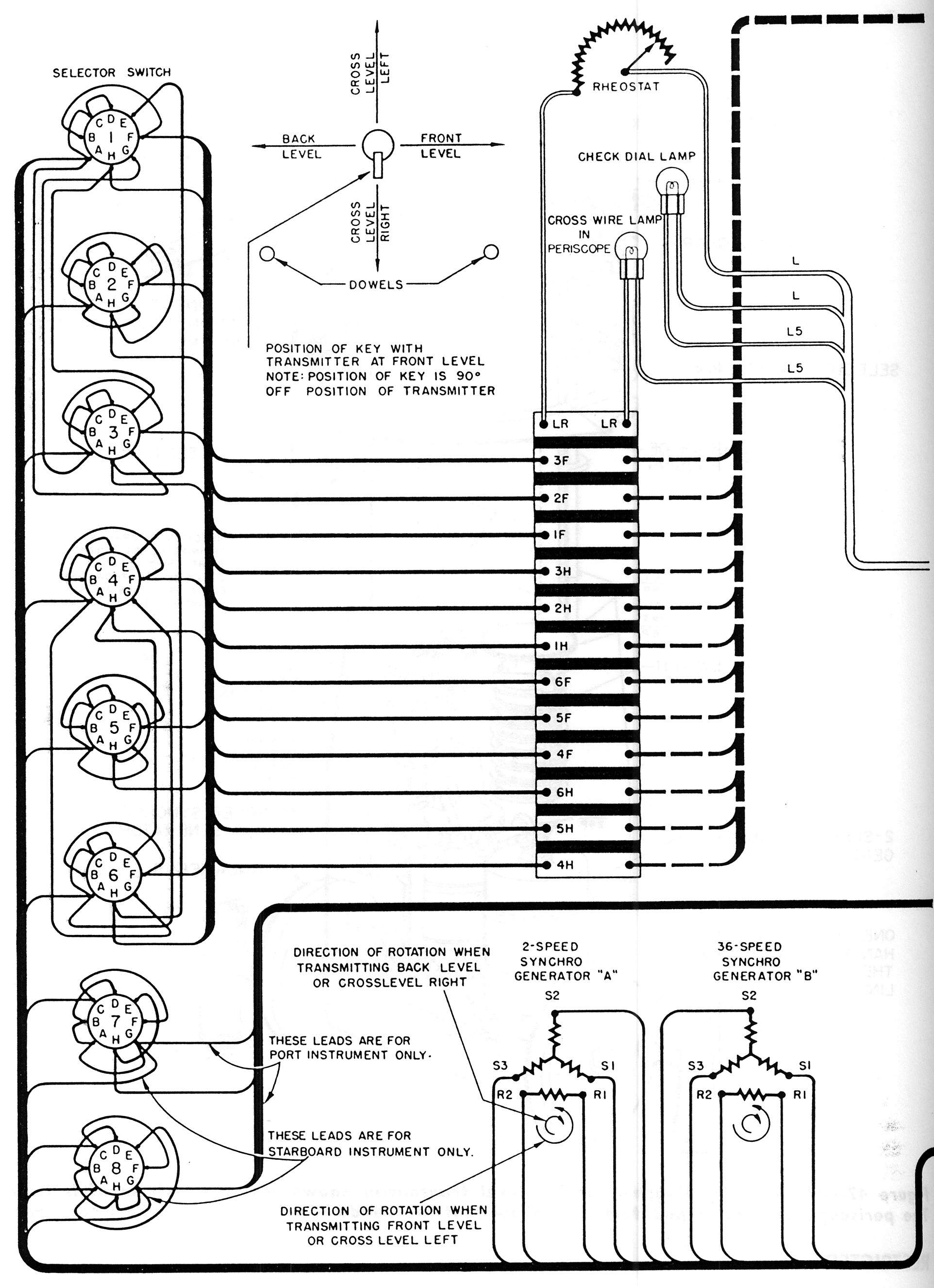
112k | INTRODUCTION What the Director Is The Gun Directors Mk.40 Mods.0 and 1 are roof-mounted type, main-battery directors located in the fire control tower (Fig.1)(OP.812),(Figs.1A),(taken aboard (BB-59), ( Fig.1B)(-BB-57),(Fig. 1C)(-BB-55) & (Fig. 1D)(-BB-61), used to obtain director train, level, and crosslevel. Each director consists of several fire-control instruments mechanically and electrically interşconnected to make one instrument-the direcştor. (See Fig.2) . What the Director Consists of: The director consists of the following prinşcipal equipment: Target designator Target bearing transmitter Training-gear drive Spotting-glass mount Periscope Mk.32 Mod.0 Two level transmitters Two periscopes Mk.30 Mod.0 Level transmitter and computer drive In addition to these instruments, other auxilşiary equipment in the fire-control tower is used in conjunction with the director. This equipşment includes the Radar Equipment Mk.27 Mod.0 (Fig.31) with the Antenna Train Drive Mk.5 Mod.0. For a complete description of how the radar equipment is used in conjunction with the director, see OP.1155 (Confidential). A Computer Mk.3 Mod.0 (Fig.22b) and Trunnion Tilt Corrector Mk.5 Mod.0 is located in the Fire Control Tower( Fig.1B) that houses the Gun Director Mk.40 Mod.0. Although these units are identified on drawşing list of material as "Level Transmitter," they may also be used to transmit crosslevel. Where the Director Is Used The Gun Director Mk.40 Mod.0 is used on BB's 55-60. The Gun Director Mk.40 Mod.1 is used on BB's 61-66. The director, located in the fire-control tower, is on the horizontal reference point; that is, its center of rotation is the horişzontal reference point for the main-battery fire şcontrol system. The distance that the director is from the vertical reference point is not conşsidered, since there is no vertical-parallax corşrection made in the director. How the Director Is Used The Gun Directors Mk.40 Mods.0 and 1 can be used to supply director train, level, and crossşlevel to the main-battery plot via the mainşbattery switchboard. The rangekeepers in plot (Fig.32) here Mk.8 Mod.9 aboard BB-56) compute gun orders and send them to the 16-in. gun turrets. On BB's 55-60(Figs.1A & 1B), the Gun Director Mk.40 Mod.0 can be used in conjunction with the Comşputer Mk.3 Mod.0 (Fig.22b) and Trunnion Tilt Corrector Mk.5 Mod.0 to supply gun orders to the 16-in. gun turrets via the auxiliary switchboard. (Fig. 3. The director furnishes director train, level, and crosslevel to the computer and trunşnion tilt corrector, which computes gun orders and sends them to the 16-in. gun turrets. For further information on how the director is used in the main-battery fire control system See: OP 856 for BB's 55-60 and OP 1378 for BB's 61-66. The director can also be used to designate surşface targets by supplying target designation to the target designation system. Inputs and Outputs The Gun Directors Mk.40 Mods.0 and 1 receive one electrical input at one- and 36-speed, target designation or antenna train. This input is transşmitted to the target designator of the director via a selector switch. The director has the following outputs (See Fig.4). 1. Director train, sent out electrically at one şand 36-speed, by the two sets of transmitters in the target bearing transmitter. One set of transşmitters is for director train; the other set is connected to the target designation system and is, therefore, for target designation. 2. Level, sent out electrically at two- and 36-şspeed. 3. Crosslevel, sent out electrically at two- and 36-speed. In addition to these outputs, the Gun Direcştor Mk.40 Mod.0 sends out director train mechanically at 24-speed to the Computer Mk.3 Plod 0 and Trunnion Tilt Corrector Mk.5 Mod 0. Difference between Mods: The difference between the Gun Director Mk.40 Mod.0 and the Mod.1 stems from the fact that the Mk.40 Mod.0 is associated with the Computer Mk.3 Mod.0 and Trunnion Tilt Corrector Mk. 5 Mod.0. The Mk.40 Mod. 1 has no associated computer-and-trunnion tilt corrector. Thus, the Mk.40 Mod.0 has a mechanical shaft transmitting director train to the computer and trunnion tilt corrector, while the Mod.1 does not. How the Director Works In order to describe the various functions of the Gun Directors Mk.40 Mods.0 and 1, this secştion is divided into two parts: The first part exşplains how the Mods.0 and 1 produce director train, level, and crosslevel. The second part deals with the Mod.0 and how it works in conjunction with the Computer Mk.3 Mod.0 and Trunnion Tilt Corrector Mk.5 Mod.0 to produce gun orders. Director Train, Level, and Crosslevel The gun director supplies director train, level, and crosslevel. These quantities are produced as follows: Director Train: This quantity is produced when the trainer turns his handwheels to get the director "on target." As the director is trained, synchro generators in the target bearing transşmitters are positioned. These generators send out director train electrically at one - and 36 şspeed. The instrument called "Target Bearing Transmitter" should be called "Director Train Transmitter," because it houses the generators that transmit director train. In this director the name "Target Bearing Transmitter" is a carryş-over from previous directors. As the trainer turns his handwheels, he also trains the leveler's and the crossleveler's periscopes and thereby keeps the leveler's sight along the line of sight and the crossleveler's sight at right angles to the line of sight at all times. Level: The leveler looks through his periscope and turns his handwheels to keep his sight ON. As he turns his handwheels, he positions two synchro generators in his level transmitter. These generators send out level electrically at two- and 36 - speed. Crosslevel: The crossleveler looks through his periscope and turns his handwheels to keep his sight on the horizon. As he turns his handşwheels, he positions two synchro generators in his transmitter. These generators send out crosslevel electrically at two - and 36- speed. In addition to the above quantities, the spotter in the director sends out the necessary "spots" by telephone. When the spotter looks through his periscope and turns his handwheel to keep his sight on the target, he keeps the trainer's sight leveled on the target, because the trainer's and spotter's sights have a common tilting mirşror operated by the spotter's handwheel. Gun Orders The Gun Director Mk.40 Mod.0 can be used in conjunction with the Computer Mk. 3 Mod. 0 and Trunnion Tilt Corrector Mk.5 Mod.0 to produce gun orders. The computer-and-trunnion tilt corşrector receives director train (mechanical), level, and crosslevel (electrical) from the director. The Computer Mk.3 Mod.0 and Trunnion Tilt Corrector Mk.5 Mod.0 produces gun train and gun elevation orders. This instrument sends gun train order (Automatic) electrically at one - and 36 - speed and gun elevation order (Automatic and Indicating) electrically at two - and 36- speed to the 16-in. gun turrets. Target Designation The Gun Directors Mk.40 Mods.0 and 1 can be used to supply target designation (director train) to the target-designation system. The director can either originate a signal or relay signals received from another station. When the director is used to originate a sigşnal, the fire-control officer designates a target and the trainer turns his handwheels to get "on target." By doing so, he positions the synchro generators in the target bearing transmitter. One set of these generators sends out target designation electrically at one- and 36-speed to the target-designation system. When the director is used to relay signals, the target designator in the director receives target designation electrically at one- and 36-speed and indicates it on dials. The trainer turns his handşwheels to match these dials, thereby training the director on the target and positioning the synchro generators in the target bearing transşmitter. One set of these generators sends out target designation electrically at one- and 36şspeed to the target-designation system. OPERATION Personnel The Gun Director Mk.40 Mods.0 and 1 requires four operators : trainer, spotter, leveler, and crossleveler.(See Fig.5). The trainer is staştioned at the trainer's handwheels. The spotter mans the elevating handwheel of the Periscope Mk.32 Mod.0. The remaining two operators man the two level (or crosslevel) transmitters, which are so designed that either can be used to obtain level or crosslevel. Thus, one of these two will act as the leveler, the other as the crossleveler. In Fig.5 the starboard level transmitter is in the level position, the port transmitter in the crosslevel position. In the fire-control towers of BB's 55-60, which house the Gun Director Mk.40 Mod.0, there are additional operators who man the comşputer and trunnion tilt corrector. For informaştion on their duties, see NAVORD OD 3175. What the Operators Do The Trainer mans the handwheels of the training-gear drive to train the director on the target either by looking through his sight or by matching dials on the target designator. When the trainer is using his sight, he turns his handwheels to keep the vertical line of the sight on the target. If the target is obscured, or if the director is receiving targetş designation signals, the trainer turns his handşwheels to match dials of the target designator. The target designator dials consist of two folşlow-the-pointer dial groups. The lower group operates at one-speed, the upper at 36-speed. The inner dials indicate the order received; the outer dials indicate actual train of the director. When the zero indexes of the outer dials are matched with the indexes of the two inner dials, the trainer has carried out the order and the direcştor is at the ordered train angle. Fig.6 shows how the dials appear when the director is receiving a typical target-designation or antenna-train signal. Note that the two inner dials have been positioned so that their indexes are away from the fixed indexes on the dial face plate. Fig.7 shows how the dials appear when the trainer has turned his handwheels to carry out the order. Note that the zero indexes of the ring dials match the indexes of the inner dial: In this example, the ring dials indicate a reading of 68░ 20'. The lower one-speed dials indicate reading of 60░ plus, the upper 36-speed dial show 8░ 20', for a total reading of 68░ 20'. The trainer's handwheels are provided with two keys. The one on the right handwheel is the train-ready contact-maker key. When the direcştor is in control, the trainer closes this key when his vertical wire is on the target, thus energizing train-ready lights at various stations. The left handwheel has a target-designation buzzer contact maker. When the director is transmitting target-designation signals, the trainer closes this key when he is on the target. Closing of the key operates buzzers at the staştions receiving the signal. The spotter mans the spotter's sight and the elevating handwheel of the Periscope Mk.32 Mod.0. The spotter keeps his sight on the target by turning the handwheel. As he does this, he automatically keeps the trainer's sight leveled on the target, because the trainer's and the spotşter's sights have a common tilting mirror operşated by the spotter's handwheel. Fig.8 shows how the spotter's sight appears when on the target. The spotter keeps his sight as shown, regardless of own ship's roll and pitch. Note that the splash to the left of the target indicates 20-nuls right-deflection "spot." Splashes to the right of the target will indicate left-deflecştion spot. Other duties of the spotter include: (1) to designate which level transmitter is to be used for obtaining level and crosslevel, and (2) to check the trainer to see that the director is trained on the target. In addition, when he is the controlling spotter, he estimates target angle, speed, etc., and transmits such informaştion by telephone circuit. The Leveler looks through his periscope and turns the handwheels of the level transmitter to keep the center cross of his sight on the horizon or middle of the target. (See Fig.9). Other normal duties include: (1) seeing that his transmitter is switched so that own periscope is measuring level, and (2), if line of sight beşcomes blocked, shifts transmitter 90░ to the right or left, as appropriate, and assumes duties of the crossleveler. When the director is in control, and the leveler is designated as the firing pointer, he performs these additional duties: 1. Operates salvo-signal contact-maker key (on left handwheel) and firing key (on right handwheel) as directed. 2. In selected-level fire, he "splits the roll" and closes the firing key for an instant when the cenşter cross of his sight crosses the target. 3. In selected-crosslevel fire, the leveler keeps the center cross of his sight on the horizon or the middle of the target. 4. Notifies spotter if center cross of leveler's sight is not on horizon or target at instant of fire. Should the leveler's sight become blocked by the ship's structure, provision is made to allow the leveler to become the crossleveler, and the crossleveler to become the leveler. The leveler, after informing the crossleveler, makes the shift by pulling down the detent pin to release it, thus permitting him to swing the transmitter 90░ to the right or left. The detent pin will engage in a hole in this new position. At the same time, the crossleveler swings his transmitter 90░ and becomes the leveler. The Periscope Mk.30 Mod.0, used with the level transmitters, has a set of elevation-angle dials, visible through a window in the instrument case. These dials consist of two conical dials mounted one on top of the other. Besides being employed in test and alignment work, these dials can be used to select a value of level or crosslevel at which to set the periscope in selected-level or selected-crosslevel fire. Fig. 10 shows how the elevation dials appear when the periscope is set for, and the level transşmitter sending out 2,145 minutes elevation. This reading is equivalent to 145 minutes, or 2░ 25', of level, since 2,000 minutes represents zero elevation. The top dial (low-speed) reads 2,100 plus, the bottom dial (high-speed) indişcates 45. The Crossleveler mans the handwheels of his transmitter. He looks through his periscope and turns his handwheels to keep the center cross of his sight on the horizon. (See Fig. 11) Other normal duties include: (1) seeing that his transmitter is switched so that own periscope is measuring crosslevel, and (2) if crossleveler's line of sight becomes blocked, shifting his transşmitter 90░ right or left, as appropriate, and assuming duties of the leveler. When the director is in control, the crossşleveler performs these additional duties: 1. Closes keys on his handwheels as directed. 2. In selected-crosslevel fire, he "splits the roll" and closes the firing key when the center cross of his sight crosses the horizon. 3. In selected-level fire, he keeps the center cross of his sight on the horizon. 4. Notifies spotter if center cross of crossşleveler's sight is not on the horizon at instant of fire. Operating Data Putting Director in Standby Condition In the standby condition, the director is ready to perform any of its functions. The usual steps necessary to place the gun director in the standby condition are: (See Fig. 12) 1. Remove periscope covers from the two Periscopes Mk.30 Mod.0. 2. Withdraw the train locking pin; then train the director to the angle at which the target is expected to appear. 3. The spotter designates the leveler and crossleveler. 4. The designated crossleveler releases his detent pin and rotates his transmitter 90░ to the crosslevel position. 5. Turn on all illumination switches. The crosswire illumination for the trainer's and spotşter's sights is controlled by rheostats mounted on the training-gear drive. The Periscope Mk.30 Mod.0 crosswire illumination is controlled by rheostats on the level transmitters. 6. Throw in all necessary switches as directed by the fire-control officer. Tracking Before tracking commences, the director is trained on the target in response to a target şdesignation or antenna-train signal. A buzzer warns the director crew when the director is reşceiving a signal on dials of the target designator. Once the director is trained on the target, the procedure is as follows: (See Fig. 12) 1. The trainer and the leveler center their crosswires on the target. 2. The crossleveler keeps his crosswires on the horizon. 3. The spotter keeps his sight on the target, and telephones estimated range, target course, target speed, etc. In addition he telephones the necessary spots and any change in target course and speed. 4. For the duties of the other operators in the fire-control tower, see: Ship's Battle Bill (Mainş Battery Fire Control Tower). Securing The following steps should be taken to secure the gun director after use: (See Fig. 12) 1. Train the director to its securing position pin. The trainer's handwheels should be moved back and forth while inserting the locking pin to insure a good seat. 2. Release the detent pin of the transmitter being used for crosslevel, and rotate the transşmitter so that it is trained to zero degrees. Insert the detent pin in this position. 3. Turn the handwheels of the level transmitşters until the elevation dials indicate 2,000 minutes (zero elevation). 4. Set all transmitting switches to the OFF position. 5. Cut off periscope crosswire-illuminating switches. Cut off the lighting switches. 6. Replace the two hood covers for the Periscope Mk.30 Mod.0. DESCRIPTION Because the Gun Director Mk.40 Mods.0 and 1 are very similar in construction, the following description applies to both. The only difference in design is pointed out in the section on the level transmitter and computer drive. Each director consists of the following units: (See Fig. 13) (1) training-gear drive and cable tube (2) target designator (3) target bearing transmitter (4) spotting-glass mount (5) Periscope Mk.32 Mod.01 (6) level transmitter and computer drive (7) two level (or crosslevel) transmitters, and (8) two Periscopes Mk.30 Mod.0. Except for the level transmitter and computer drive, all these units are identical for both modifications. This unit transmits director train in the case of the Mod.0, whereas in the Mod.1 there is no transmission of this quantity. The spotting glass mount was originally deşsigned to support a spotting glass. On the presşent installations, the spotting glass has been replaced by a periscope. Therefore, the spotting glass mount is actually a periscope mount. Training-Gear Drive and Cable Tube The training-gear drive, which contains the trainer's handwheels, transmits rotation of the handwheels to the target bearşing transmitter, to the target designator and, by means of shafting in the target designator, to the training gear. The training-gear drive consists of two secştions, the housing and the rotating head. The housing is a fork-shaped aluminum casting which houses the handwheels, rheostats, gears, and shafts. The handwheels, located on the forward (trainer's) side of the training-gear drive, are approximately 42 in. from the fireş control flat. There are two firing keys. The one on the right handwheel is the train-ready conştact maker, and the one on the left is the target şdesignation-buzzer contact maker. Rotation of the handwheels is transmitted through bevel gears and shafts to both ends of the training şgear drive. Mounting pads at these ends are provided to bolt the training-gear drive to the target bearing transmitter and to the tarşget designator. Two covers are bolted to the underside of the training-gear drive. The left cover gives access to the micro adjustment of the drive to the tarşget bearing transmitter. The other cover gives access to the bevel gears connecting to the target designator. Lubrication fittings screwed to the housing are provided for bearing lubrication. Two rheostats, one for the trainer and one for the spotter, are mounted on the front and rear of the training-gear drive. These rheostats are used by the trainer and the spotter to control the crossline illumination of their respective sights. Cables connect these rheostats to the Periscope Mk 32 Mod 0. The rotating head, a cast-aluminum tube fitşting over the cable tube and bolted to the trainşing-g,ear-drive housing, contains terminal tubes and mounting pads for wiring branch boxes and for several telephone jack boxes. The rotating head has a pad which mounts the spotter's teleşphone selector switch. (Fig.14) The cable tube is a steel tube screwed into a cast flange which is bolted to the fire-control flat. The cable tube houses the supply cables for the training-gear drive, target designator, and tarşget bearing transmitter. Pads on the cable tube mount additional telephone jack boxes. Fig.15 shows the relationship between the rotating head, cable tube, and cast flange. The kick pipe shown is a metal pipe which proştects the telephone cables to the jack boxes. Target Designator The main purpose of the target designator is to enable the trainer to train the director in accordance with electrical target-designation or antenna-train signals. The instrument also conştains intermediate shafting which transmits rotation from the trainer's handwheels to the training gear. The instrument, which is approximately 28 inches high, is suspended from the training gear. A flange at the bottom of the instrument is bolted to the left end of the training-gear drive. The target designator consists of a cast şaluminum case housing the dial-and-motor unit, gearing, and shafting. The case has a dial window on the front and a case cover on the rear which gives access to the dial-and-motor unit. Two lightwells on the left side of the case provide dial illumination. Supply leads to the synchro motors and lightwells enter through a terminal tube at the bottom of the case. An air-inlet valve near the top of the case and a drain plug at the bottom are used for drying out the instrument. Four lubrication fittings screwed into the case provide means of lubricatşing the bearings. The case has internal mounting pads and flanges for supporting the dial-and-şmotor unit and the intermediate shafting. A cast-aluminum plate, which mounts the inştermediate gearing to the overhead internal gear, is fastened to the top of the case. The transmission gears of the intermediate gearing are enclosed in an oil-tight compartment in the upper part of the case. Oil is adşmitted into this compartment through a lubrişcating fitting. A drain plug is provided for drainşing out this compartment. The dial-and-motor unit consists of a cast şaluminum frame on which are mounted two Synchro Motors, Mk.4, Type 5F, the follow-the-şpointer dial groups, the terminal boards, gearing, and shafting. The synchro motors, fixed to the frame with motor clamps, operate at one- and 36-speed. These motors receive the electrical signal of target designation or antenna train and position the inner dials of the follow-the-pointer dial groups. The ring dials are driven mechanically by rotation of the trainer's hand wheels. Fig.16 shows the dial face of the target designator. The lower dial group operates at one speed, the upper at 36-speed. The dials are black, with white translucent figures. The one-speed ring dial is graduated every five degrees, with every 10░ numbered from zero to 360. The 36-speed ring dial is graduated every ten minutes and numbered every degree from zero to 10░. Both inner dials have an index marking. The dial face plate has two fixed indexes, one for each dial group. The instrument terminal board is attached to the frame of the dial-and-motor unit. Wiring: The synchro motors and lightwells are wired to the instrument terşminal board. Gearing arrangement of the target designator. This instrument receives its mechanical input from the trainer's handwheels by means of gearing and shafting in the training-gear drive. This rotation is transşmitted to the training pinion via the intermedişate gearing and shafting and to the one- and 36-speed follow-the-pointer ring dials. A micro adjustment is provided in the shafting for lining up the ring dials with the train of the director. Target Bearing Transmitter The main purpose of the target bearing transşmitter is to convert a mechanical input of direcştor train into an electrical output. The instrument, which is approximately 28 inches high, has a flange at the top which is bolted to the training gear. A flange at the botştom of the instrument is bolted to the right end of the training-gear drive. The target bearing transmitter consists of a cast-aluminum case which houses the generator unit and the input gearing. The case has an access cover which, when reşmoved, exposes the internal "works" of the inşstrument. Two terminal tubes at the bottom of the case convey the supply wires that connect to the synchro generators. An air-inlet valve near the top of the case and a drain plug at the bottom are provided for drying out the instrument. The case has internal mounting pads which support the generator unit. The generator unit consists of a cast-aluminum frame on which are mounted two sets of one- and 36-speed synchro generators, terminal strips, gearing, and shafting. The Synşchro Generators Mk.2 Type 6G are held in place by clamps. The two generators at the top operşate at one-speed, the bottom two at 36-speed. One set of these generators is connected to the director train circuit and the other set to the target designation circuit. Wiring: the synchro generators are wired to the terminal strips. Gearing: The target bearing transmitter receives its input from the trainer's handwheels by means of gearing and shafting in the training-gear drive. This rotation is transşmitted to the 36-speed generators by means of bevel gears and to the one-speed generators by means of worms and wormwheels. Two sets of index marks, one in the 36-speed shafting and the other in the one-speed shafting, are provided for lining up the one-speed synchro generators with the 36-speed generators. An Oldham couşpling in the gearing permits removal of the generator unit. Spotting-Glass Mount The spotting-glass mount, originally designed to support the Spotting Glass Mk.9 Mod.0 (Fig.33) now serves as a mount for the Periscope Mk.32 Mod.0. The mount consists of several parts and subşassemblies, some of which are bolted to the roof of the fire-control tower and, therefore, are staştionary. Other parts of the mount are attached to the Periscope Mk.32 Mod.0 and, therefore, train with it. The stationary parts are the base ring, the lower-roller-path frame, the training-gear liner, and the overhead internal gear. (Fig.17) The base ring, about 64 inches in diameter, is bolted to the top of the tower and is used as a base for the lower roller-path frame. This frame, bolted to the base ring, mounts the lower roller path. The roller path separates the lower roller-path frame from the rotating structure. Two rubber bumpers mounted on the lower roller-path frames act as limit stops for the rotating strucşture. The training-gear liner, a round steel plate bolted to the under side of the roof, is used as a base for the overhead internal gear. The purşpose of this overhead internal gear is explained later in this section in connection with the rotatşing structure. The rotating structure, which supports the Periscope Mk.32 Mod.0 consists of the carriage and the training-gear assembly. (See Fig.17) The carriage is a mushroom-shaped steel casting that rides on rollers on the lower roller-path frame. Two sets of roller bearings separate the stationary parts from the carriage. These sets are the roller-path rollers located near the outer edge of the carriage, and the radial bearings, near the neck of the structure. The packing (held in place near the top of the periscope by a packing ring) and the mount shield (a two-şsection collar that fits around the periscope) preşvent water from leaking into the fire-control tower. A weather strip that is fastened to the outer edge of the carriage and fits into a groove in the lower roller-path frame prevents water from leaking onto the roller path. The upper surface of the carriage has two steel covers used for inspection and maintenance of the roller-path rollers. Three jacking screws, protected by caps, are installed in the top of the structure and are used to jack up the carriage. Four additional jacking screws near the outer edge of the carriage are used for removing the upper roller path from the carşriage. A lug projecting beyond the diameter of the carriage hits against the stationary rubber bumpers of the lower roller-path frame, thereby limiting the rotation of the carriage to 300░ş 150░ either side of the fore-and-aft axis of the ship. The training-gear assembly, which mounts the training gear and the locking pin, consists of three cast-steel plates bolted together to form one large circular plate that is held fast to the carriage by a large nut. On the bottom surface are dowel pins and studs for bolting the assembly to the target bearing transmitter and to the target designators. The training pinion of the target designator meshes with the overhead internal gear, causşing the rotating structure and the Periscope Mk.32 Mod.0 to train. This movement is transmitted to the training gear and to the level transmitter and computer drive, which in turn transmits the rotation to the port and starboard level transşmitters. The locking pin fits into a detent in the trainşing-gear liner when the mount is in its secure position. When the director is to be used, the pin can be disengaged by pulling down the detent knob to which the pin is attached, and rotating the knob about ╝ turn. The Periscope Mk.32 Mod.0 is attached to the rotating structure by means of the periscope support bracket which is bolted to the top of the mount. Periscope Mk.32 Mod.0 The Periscope Mk.32 Mod.0 is a "two-in-one" periscope, containing both the trainer's and the spotter's sights. The arrangement of the optical system allows both the trainer and the spotter to see the target at the same time. (Fig.18) The optical characteristics of the periscope are: Magnificationůůůůůůůůůů. 12 times True fieldůůůůůůůůůůůů.. 4░ 10' Exit pupilůůůůůůůůůůůů.. 5.0 mm Eye distanceůůůůůůůůůůů. 38.0 mm Maximum elevation of line of sightůů..15░ Maximum depression of line of sightůů15 ░ The periscope is made up of four parts: the body, mirror-mount assembly, lower casing, and head. (See Fig.18) The periscope body consists of a steel tube, nine inches in diameter and approximately 60 inches long, in which are mounted two optical tubes and shafting. One of the optical tubes houses the lenses for the trainer's sight, and the other tube houses the lenses for the spotter's sight. The shafting, which runs the whole length of the periscope body, connects the spotter's handwheel with the mirror mount. A collar, attached to the mid-section of the periscope body, is used to fasten the periscope to the supşport bracket. (See Fig.17) The mirror mount, which contains the end reflectors and the tilting mechanism, is a small assembly that fits into the upper end of the periscope body. The two end reflectors face the ends of the optical tubes and are mounted on a frame that pivots on a horizontal axis. A gear segment attached to this frame is driven by the tilting mechanism of the mirror mount. The tilting mechanism consists of a shaft and the elevating nut to which a rack is attached. The lower end of the shaft is coupled to the elevating shafting of the periscope body; the upper end is a worm that meshes with the elevating nut. Rotation of the elevating shafting drives the elevating nut up or down, depending upon the direction of rotation of the shaft. As the elevatşing nut moves, the rack attached to the nut drives the gear segment of the mirror mount. Thus, rotation of the spotter's handwheel, transşmitted by means of elevating shafting in the periscope body, raises or lowers the elevating nut, thereby tilting the end reflector. Tilting of the end reflectors elevates or depresses the trainşer's and spotter's lines of sight. The lower casing is an assembly that fits over the lower end of the periscope body and is held fast to it by a nut. Two round sockets inside the casing fit over the optical tubes of the periscope body. The casing contains the trainer's and spotşter's eyepieces, two prisms, two lamps, and the spotter's handwheel. The eyepieces are mounted on opposite sides of the casing, and each one is equipped with a ray filter knob and a density knob. The ray filter knob allows the operator to use the red, the yellow, or the clear filters, or the polarizing filters. The density knob rotates the polarizing filter nearer the eye with respect to the fixed polarizing filter and so varies the light transmission of the combination from maximum to minimum. When the planes of polarization of these two filters are parallel, that is, when the transmission is maximum, they are oriented to reduce to a minimum the glare from a horişzontal surface. The prisms, one for the trainer and one for the spotter, are mounted in back of each eyepiece and directly below the optical tubes. The illuminating lamps, accessible through removable covers, are mounted above the eyeşpieces and provide illumination for the crossşwires of each sight. The intensity of these lamps is regulated by means of the rheostats mounted on the training-gear drive. Two terminal tubes attached to the bottom of the lower casing are used for the supply wires leadşing from the rheostats to the lamps. The spotter's handwheel, mounted on the side of the lower casing, is connected by bevel gears with the elevating shafting in the periscope body. By turning the handwheel, the spotter controls the "level" of the periscope when the ship rolls and pitches, thus keeping trainer's sight leveled on the target. Mounted on the shaft of the handwheel is a limit stop. The stop consists of a collar that has a projecting lug. This lug hits against a stationary bumper atştached to the lower casing. By means of this limit stop, rotation of the spotter's handwheel is limited to one revolution, allowing a maximum tilt of 20░ of the end reflectors above or below the horizontal line. Note: Optical characteristics of the periscope gives maximum light-gathering power for only 15░ above and below the horizontal, although the limit stops are set for 20░. Two valves, one for gas inlet and the other for outlet, are accessible through holes in the level transmitter instrument case and are used to dry out the instruments. The periscope head, carrying the window comşmon to both lens systems, fits over the upper end of the periscope. The shell of the periscope head projects over the window to provide shadşing for it. Level Transmitter and Computer Drive The purpose of the level transmitter and comşputer drive of the Gun Director Mk.40 Mod.0 is to transmit director train, received from the training gear, to the port and starboard level (or crosslevel) transmitters and to the Compuşter Mk.3 Mod.0 and Trunnion Tilt Corrector Mk.5 Mod.0. The drive consists of a "T"-shaped casting bolted to a lining on the under side of the roof of the fire-control tower. The casting houses three shafts, one of which mounts a spur pinion and a bevel gear. (Fig.20) The pinion meshes with the training gear of the spotting-glass mount, and the bevel gear drives two other bevel rears mounted opposite to each other. The horişzontal shafts connect by means of micro-adjustşment couplings with the level (or crosslevel) transmitters. The vertical shaft connects by means of a micro-adjustment coupling with the computer-and-trunnion tilt corrector. With one exception, the level transmitter and computer drive of the Gun Director Mk.40 Mod.1 is idenştical to the one described above for the Mod.0. The level transmitter and computer drive of the Gun Director Mk.40 Mod.1 has a cap bolted to the bottom of the unit and does not have the vertical shaft used in the Mod.0. Level (or Crosslevel) Transmitters The Gun Directors Mk.40 Mods.0 and 1 are equipped with two level transmitters one on the port side and the other on the starboard side of the fire-control tower. The level transmitter (See Fig.21) converts a mechanical input of level or crosslevel into an electrical output. Also, the transmitter serves as support for the Periscope Mk.30 Mod.0. In order to simplify the description of the levcl transmitter, the instrument is broken down into four parts, the periscope collar and hood, the train-input assembly, the rotating assembly, and the cable tube. The level transmitter (See Fig.21) & (Fig.22) The periscope collar and hood: The periscope, collar, a conical steel tube bolted to a liner on top of the fire-control tower (See Fig.22) act as a weather shield for the instrument. Packing in the upper part of the collar fits snugly around the periscope and is held in place by a retainer and protected by a gasket. A grease fitting on the periscope collar is used to lubricate the packing. The periscope cover fitting over the periscope collar protects the periscope window when the director is secured. The train-input assembly: This assembly, which relays director train from the level transmitter and computer drive to the rotating assembly, is a round aluminum casting secured with three bolts to a steel liner on the under side of the roof of the tower. The assembly contains the training worm, which connects by means of a coupling to the splined shaft leading from the level transmitter and computer drive. Grease fittings are provided to lubricate the training worm and its bearings. The lower edge of the train-input assembly has an azimuth dial on its circumference, calişbrated every degree and numbered every five degrees from zero to 360░. This dial is used to line up the level transmitter with the train sysştem when the level transmitter is installed in the tower, and when adjustments and tests are made. Two fittings are provided on the lower surface of the assembly for lubricating the bearings that separate the train-input assembly from the rotating assembly. The rotating assembly: This assembly is described in three parts, the periscope-housşing assembly, the instrument case, and the mechanism. The periscope-housing assembly Fig.22 consists mainly of the periscope housing and the train gear. The housing is a cast-steel tube that projects through the roof of the fire-control tower and fits around the periscope. Although the housing is not fastened to the tower or to the periscope, its upper part guides the periscope. The housing is held in place by bearings that separate it from the train-input assembly and from the instrument case. The train gear which meshes with the training worm is fastened to the periscope housing by a large nut. Thus, the periscope and the housing can be trained indeşpendently of each other because there is no direct connection between them. However, the perişscope housing can only be trained by rotation of the training worm. A ring, approximately 18 inches in diameter, is attached to the bottom of the periscope housşing. This ring has gear teeth, machined into its inside circumference, that mesh with the selecştor-switch input pinion. This pinion is described later in connection with the mechanism of the instrument. The ring also has four detents in its lower edge, 90░ apart, into which fits the detent pin of the instrument case. When the detent pin engages one of these detents, rotation of the periscope-housing assembly, imparted by the training worm, causes the instrument case to train. Thus, as the case is trained, the Perişscope Mk.30 Mod.0 trains, since it is fastened to the instrument case by means of four blocks and a screw dowel. The instrument case (See Fig.23) consists of an upper and a lower section. The upper secştion, approximately eight inches in diameter at the top and widening out to about 10 by 11 inches at the bottom, hangs from the periscope şhousing assembly by a ball-bearing-mounted plate. The weight of the periscope in the instrument case is supported by four stop blocks. The azişmuth pin keys the periscope to the instrument case and transfers the torque to drive the periscope. The azimuth pointer, used in connection with the azimuth dial of the train-input assembly, is bolted to the instrument case. Also bolted to the case is the detent-pin assembly. The detent pin, normally held in an up position by a spring, is connected to a knob that can be pulled down to disengage the detent pin when the level transşmitter is to be rotated 90░ to the level or crossşlevel position. The rectangular portion of the upper section of the case contains the mechanism of the level transmitter. Mounting pads and bearings are provided in the case for the various units of the mechanism. An air-inlet valve on the side of the case and a drain plug at the bottom are used for drying out the instrument. The case has two access covers bolted to it. The rear cover is a solid aluminum casting which gives access to the limit stop and to terminal strips for the synchro generators and lighting circuits. The front cover, also an aluminum casting, is equipped with the ON light. This light, visible through a small circular window in the cover, goes ON when the instrument is transmitting level. Another small window, mounted at eyeşlevel in the front cover, gives view to the elevaştion dials of the Periscope Mk.30 Mod.0. The lower section of the instrument case (See Fig.23) is an aluminum casting that bolts to the under side of the upper section. The lower secştion contains fuses, which are accessible through the fuse door held shut by two butterfly nuts. The mechanism of the level transmitter conşsists of the handwheels and firing keys, limit stop, two synchro generators, selector switch, illumination transformer, and ON light (coşordinating light), crosswire-illumination rheoşstat, gearing, and shafting. (See Fig.23) The handwheels, located approximately 42 inches from the fire-control flat, are equipped with firing keys. The one on the right handwheel is the firing key, and the one on the left is the salvo-signal-control-maker key. The shaft conşnecting the handwheels mounts a limit stop which is set to allow a maximum deflection of the periscope mirror 19░ above and below the horizontal line of sight. Rotation of the handwheels is transmitted by means of gears, shafts, and an Oldham coupling to tilt the mirror of the Periscope Mk.30 Mod.0. One revolution of the handwheels is equivalent to five degrees elevation or depression of the sight. Level (or crosslevel) can be read on the elevation dials, which are part of the periscope. The handwheels are also geared to the two şand 36-speed synchro generators. The two Generators, Mk.2, Type 6G, transmit level or crosslevel, depending on the position of the selector switch. The selector switch is geared by the selector şswitch pinion to the internal gear of the perişscope housing and is operated by the relative position of the instrument with respect to the periscope housing. For example, when the level transmitter is set for level, the detent pin on the instrument case is engaged in one of the detents of the periscope housing, and the selecştor switch is in the "level" position. When the level transmitter is changed to the "crosslevel" position, the detent pin is disenşgaged, and the instrument is rotated 90░. When this is done, the periscope housing and the interşnal gear remain stationary, causing the selector şswitch pinion to rotate. Rotation of the pinion sets the selector switch to "crosslevel." The selector switch, in addition to channeling the electrical output of the synchro generators to the proper terminals in order to transmit level or crosslevel, operates the ON light of the instruşment when transmitting level. Thus, the ON light indicates to the operator when his instruşment is in the level position. A rheostat bolted to the right side of the instrument case (See Fig.21) is used to turn on and control the intensity of illumination of the periscope crosswires. The knob of the rheostat has three positions: OFF, DIM, and BRIGHT. The cable tube of the level transmitter is a steel tube screwed into a cast flange which is bolted to the fire-control flat. The cable tube houses the supply wires to the level transmitter. Gearing and Wiring: Fig.24 shows the gearşing for the level transmitter. The handwheels are geared to the two- and 36-speed synchro motors and to the input shaft of the Periscope Mk.30 Mod.0. The instrument is trained by rotaştion received from the trainer's handwheels via the level transmitter and computer drive. The selector switch is positioned by rotation of the selector-switch pinion. This switch has four positions: "back level," "front level," "crosslevel right," and "crosslevel left." These positions correspond to the positions of the transmitter with respect to its original posiştion with respect to the director. For example, in "back level," the transmitter and periscope has been rotated 180░ from its zero position. "Crosslevel left" means that the periscope has been rotated 90░ to the left of the zero position. This pinion receives its rotation as the instruşment is rotated from the level to the crosslevel position or vice versa. Fig.25 show how the synchro generators and lamps are wired to the terminal boards. The selector switch channels the output of the synşchro generators in the level transmitter so that the instrument will send out level when the inşstrument is in the "level" position and crosslevel when the instrument is in the crosslevel position. Periscope Mk.30 Mod.0 A Periscope Mk.30 Mod.0 is associated with each of the level transmitters. The optical characteristics of the periscope are: Magnificationůůůůůůůůůůů12 times True fieldůůůůůůůůůůůůů3░ 45' Exit pupilůůůůůůůůůůůůů.5 mm Eye distanceůůůůůůůůůůůů30 mm Maximum elevation of line of sightůůů15░ Maximum depression of line of sightůů..15░ The periscope is made up of five parts, the body, the mirror-mount assembly, head, lower casing, assembly, and gear-case assembly. (See Fig.27) The periscope body consists of a steel tube, seven inches in diameter and approximately 32 inches long, in which are mounted the optical tube and elevating shafting. The optical tube (See Fig.27) houses the lenses of the instruşments. The elevating shafting, which runs the whole length of the periscope body, transmits rotation from the leveler's handwheels to the mirror-mount assembly. The mirror-mount assembly, which contains the end reflector and the tilting mechanism, fits into the upper end of the periscope body. The end reflector faces the end of the optical tube and is mounted on a frame that pivots on a horişzontal axis. A gear segment attached to this frame is positioned by the gear rack of the tiltşing mechanism. This mechanism consists of the shaft, elevating nut that has a rack attached to it, and limit stop. The lower end of the shaft is coupled to the elevating shafting in the periscope body; the upper end is a worm that meshes with the eleşvating nut. (See Fig.28) Rotation of the elevating shafting drives the elevating nut up and down, depending upon the direction of rotation of the operator's handwheels. As the elevating nut moves, a gear rack attached to the nut positions the gear segment mounted on the mirror mount. A screw-type limit stop in the elevating shaftşing limits movement of the tilting mechanism. The stops are set to limit tilt of the end reflector to 25░ above and below the horizontal line. The periscope head fits over the periscope body and is held in place by a nut. The head encases the mirror-mount assembly and protects the periscope against the weather. The periscope window is mounted on this head, directly m front of the end reflector. The lower casing is an assembly that fits over the bottom end of the periscope body and is held fast to it by a nut. (See Fig.27) The upper part of this assembly consists of a steel tube with a projecting collar used for attaching the periscope to the level transmitter. The bottom part of the lower casing contains the leveler's eyepiece, a prism, a lamp, and shafting, that connects the gear-case assembly with the shafting of the periscope body. The leveler's eyepiece is equipped with a ray -filter knob and a density knob. The ray-filter knob allows the operator to use either the red, yellow, or clear filters, or the polarizing filters. The density knob rotates the polarizing filter nearer the eye with respect to the fixed polarizşing filter and so varies the light transmission of the combination from maximum to minimum. When the planes of polarization of these two filters are parallel, that is, when the transmisşsion is maximum, they are oriented to reduce to a minimum the glare from a horizontal surface. The prism is mounted in back of the eyepiece and directly below the optical tube. The lamp, accessible through a removable cover, is mounted below the eyepiece and provides illumination for the cross-wires of the sight. The intensity of this lamp is regulated by means of the rheostat mounted on the level transmitter. A terminal tube attached to the bottom of the lower casing conveys the supply leads running from the rheostat to the lamp. Two valves, one for gas inlet and the other for outlet, are mounted on the side of the lower casing assemşbly and are used to dry out the periscope. The gear-case assembly, bolted to the under side of the lower casing, contains the elevation dials, gearing, and shafting.(See Fig.28) A shaft that projects from the bottom of the gear şcase assembly receives rotation from the levelşer's handwheels via gearing and a coupling in the level transmitter. This shaft is connected to the elevation dials by means of gearing. The elevation dials are two cone-shaped, chromium-plated dials, with calibrations and figures engraved on them. The top (coarse) dial, which gives a direct reading of the angle of tilt of the mirror, is calibrated and numbered every 100 minutes from 1,000 to 3,000 minutes. The bottom (fine) dial, which rotates at 20 times the speed of the top dial, is calibrated every minute and numbered every five minutes from zero to 100 minutes. Both dials are read against a fixed index. Gearing for the Director The various units of the director are mechanically connected. The trainer's handşwheels are geared to the training pinion of the director. When the handwheels are turned, the training pinion rolls within the overhead interşnal gear. This causes the training gear to rotate and transmit its motion (director train) to the two level transmitters by means of connecting shafting. The trainer's handwheels are also mechanically connected by means of gearing and shafting to the synchro generators in the target hearing transmitter and to the ring dials of the target designator. The handwheels of each level transmitter are mechanically connected by means of gearing and shafting to the elevating mechanism of the Periscope Mk 32 Mod 0. The mirror of the periscope is tilted by the tilting mechanism. The handşwheels are also mechanically connected to the synchro generators in the level transmitter. |
Photo & Text: Taken from/based on: OP812. Submitted by: Pieter Bakels. | |
| Back To US Battleship Construction Index | Back To The Main Photo Index | Back To The Battleship Photo Index Page |
This page is created by Pieter Bakels and Michael Mohl & maintained by Michael Mohl
All Pages ę 1996 - 2025, by Paul R. Yarnall NavSource Naval History. All Rights Reserved.