| Click On Image For Full Size Image |
Size | Image Description | Contributed By And/Or Copyright |
|
|---|---|---|---|---|
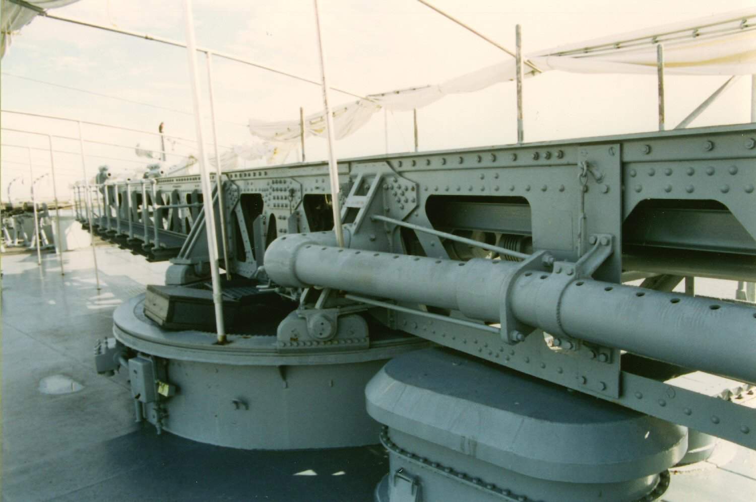 |
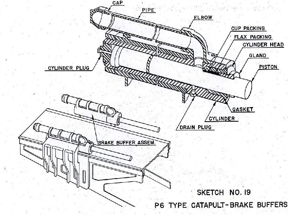
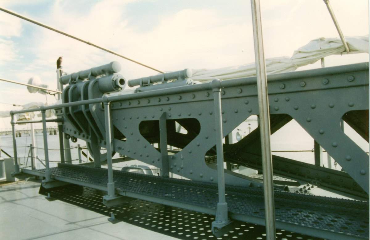
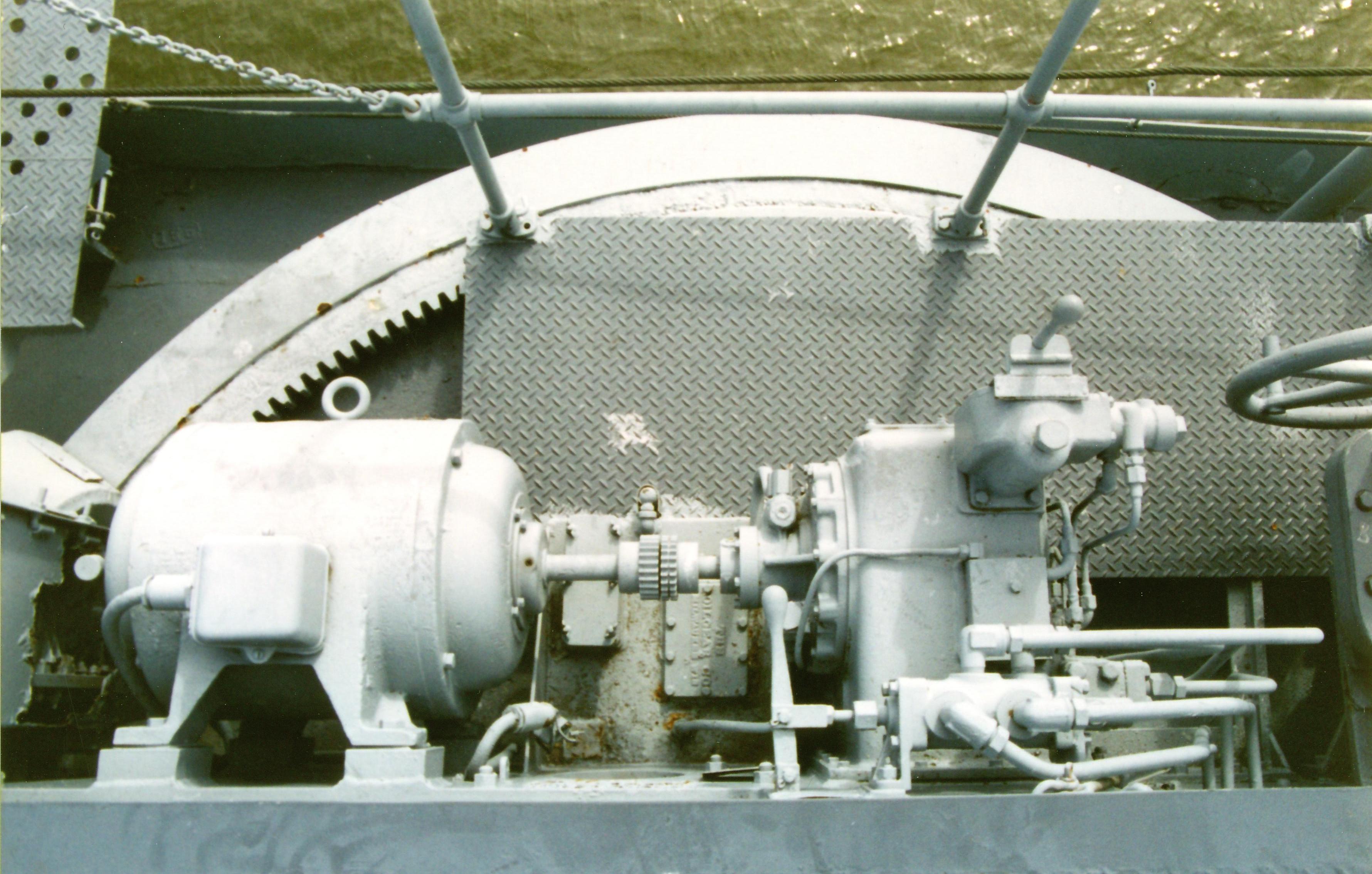
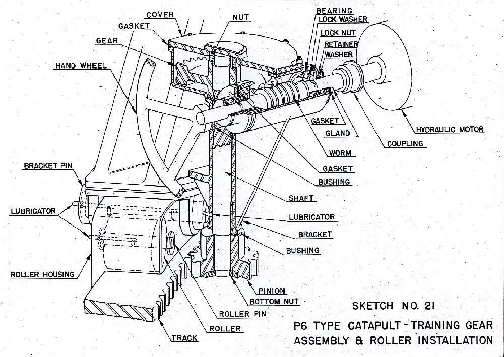
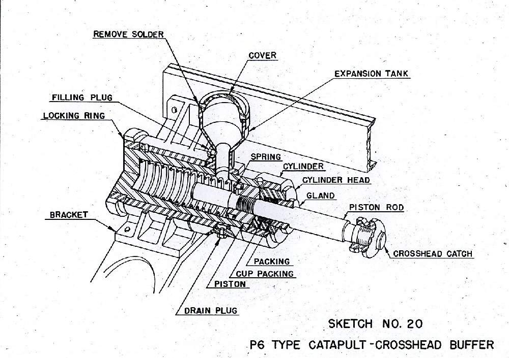
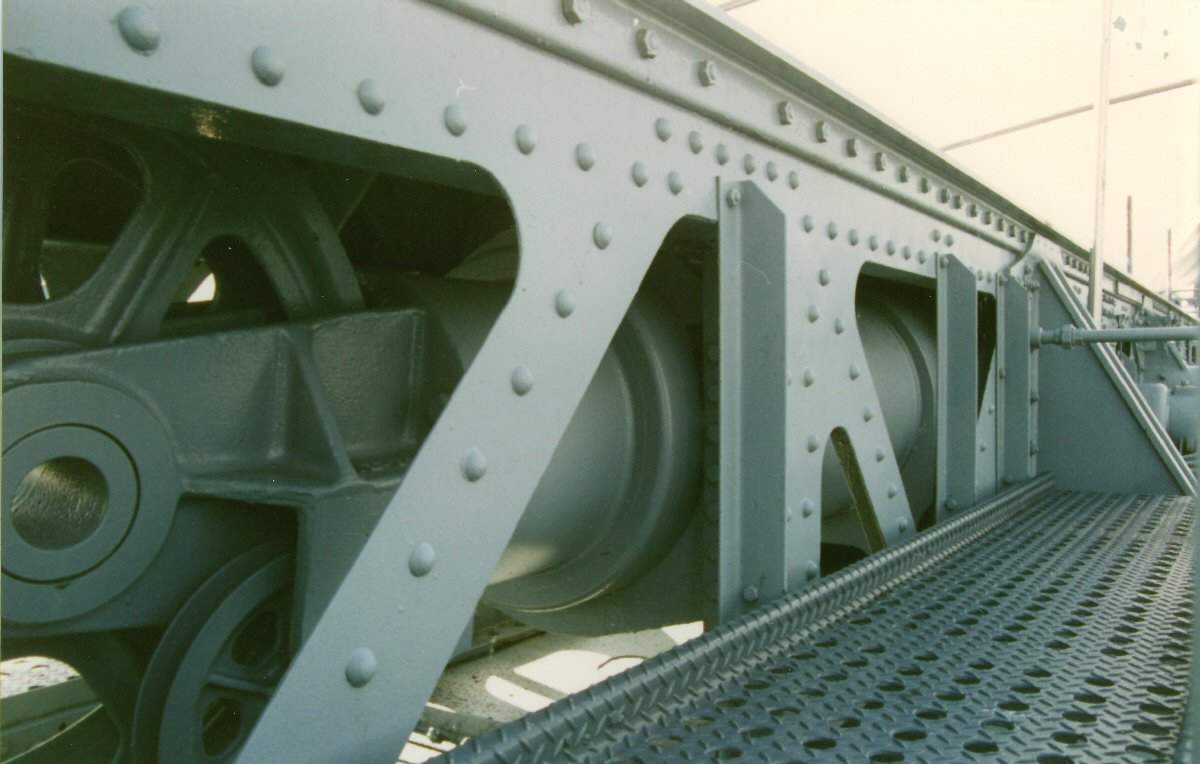
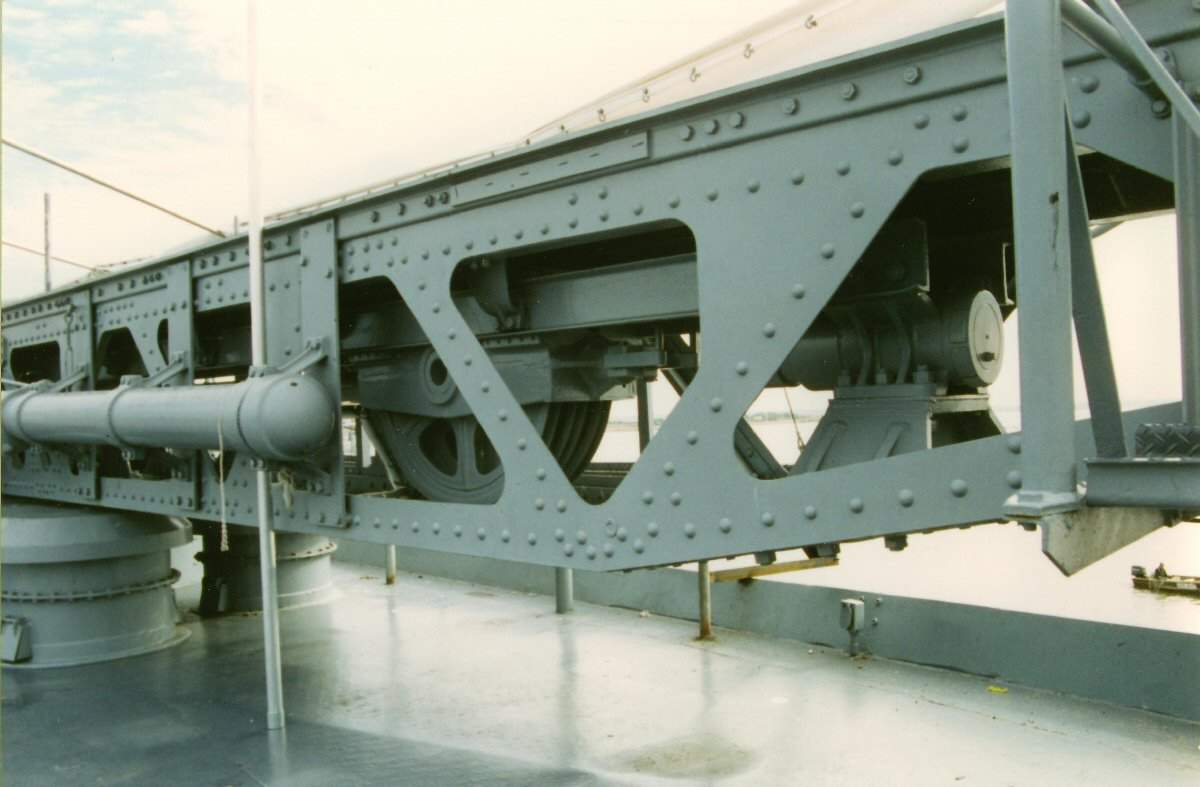
95k | AIRCAFT STOWAGE Note: All photos were taken aboard the Alabama (BB-60) by Pieter Bakels in 1993. Type P Mark 6 catapult with gun Mark VI Modification 1. It was necessary to mount the aircraft float in a slightly nose-down attitude in order to allow the keel to leave the launching car without structural interference at the end of the catapulting run. As a result, the angle of attack was small and at the instant the aircraft left the car was but a small fraction of the weight. Consequently, if the elevator control was held in neutral, the aircraft lost altitude rapidly and could strike the water. If the control stick was moved sharply backward during this descent, the angle of attack was decreased so that the lift was somewhat greater than the weight, but the downward motion was not immediately checked because of the downward momentum that had been attained. Both of the foregoing methods of control were obviously objectionable. However, extensive experience had shown that when the control stick was held well back during the entire launching run, there would be a minimum delay in increasing the angle of attack at the end of the run and a minimum loss of altitude. This control was recommended in all cases, especially with fully loaded aircraft and with little or no head wind. As soon as the aircraft was flying level or climbing, the pilot had to ease the control stick forward and exercise all controls as under normal conditions. The aileron and rudder positions were less important than the elevator position but had to be noted. The ailerons were normally kept in neutral and the rudder in the normal flight position. In general, flaps would be in full down position during a launch unless instructions to the contrary had been issued. Elevator tabs, if installed, would be in neutral or set to produce a slightly tail-heavy condition. The adjustable stabilizer, if installed, would be set to produce a slightly tail-heavy condition. Rudder tab, if installed, had to be set in neutral. A water rudder, if installed, had to be disconnected at the time of catapult launching. When not in use, the breech mechanism had to be kept closed and covered by a canvas cover. The firing mechanism had to be removed from the breechblock after firing, and assembled in place only when aircraft were to be launched or no load shots were to be fired. When in place, the firing mechanism had to be locked by the safety latch until ready to fire. In catapult guns Mk.VII and Mk.VI Mod.1 the powder gases when leaving the exhaust casing entered the blast reducer, which consisted of an eight-inch pipe with holes spaced on its upper side throughout its entire length. The gases expanded in the blast reducer and escaped through the holes with reduced velocity. The cartridge case used was the 5-inch, Mk.III. The primer was Mk.XIV Mod.1. The ignition charge of three hundred gram of black powder was contained in a silk bag, made up in doughnut form and placed around the primer at the bottom of the case. The smokeless powder charge was placed on top of the ignition charge. On top of the powder came a pyralin washer and then the distance piece. The mouth of the case was sealed by a cork plug which was pushed down on the distance piece. The contents of the cartridge were stencilled on the case, and a powder tag was attached to the distance piece. The launching cable consisted of a 1-1/8 inch ungalvanized wire rope, comprising six strands of thirty-seven wires to the strand and a hemp core. As the wire rope was not galvanized, special attention had to be paid to keeping it well greased and free from dust. The seaplane was accelerated to flying speed on a launching car, guided along the catapult by means of tracks. The launching car was equipped with slipper shoes which provided the necessary bearing surfaces for the car and the load to slide down the track. The slipper shoes were made of a phenolic composition that required the catapult track to be free from corrosion and pitting both on the upper and lower surfaces. When the track was kept highly polished on all its surfaces the composition slipper shoes lasted much longer than the metal slippers of the same dimensions. Preparatory to launching, the car was secured in battery position by a tension ring and by two safety pins. The tension ring was made of steel and was designed to break at a load less than a given amount under the combined load of the preliminary tension in the main cable and the pull of the propeller running with wide open throttle. After the aircraft and launching car were in battery position and the tension ring and safety pins were in place the tensioning mechanism had to be used to obtain the preliminary tension in the main cable. The engine would then be warmed up and run full out. After the engine had run with open throttle an attempt had to be made to pull out the safety pins. If they came out and went back readily, the tension ring was considered as checked against defects. Actual release of the launching car was effected by the automatic breaking of the tension ring when the launching car started down the track. The aircraft was held on the launching car by means of the "J" hooks on the saddle and the release lever rotating out and down from in front of the towing fitting after the launching car had moved forward approximately one foot, and the "J" hooks permitted the float to slide forward while the car was being stopped by the buffers. The launching car was stopped at the end of its run by two hydraulic track buffers mounted on the catapult structure. The function of the small car buffers was to reduce the shock of the impact with the large track buffers. Each car buffer was prevented from creeping back into the cylinder during a launching by a snap ring installed in the cylinder head, which gripped the piston rod in a shallow groove. The mechanism training the catapult and retracting the launching car consisted of an electric motor and controller, with a selective clutch for driving either the pinion gear for training or the sprocket chain for car retracting. The training and retracting gear on catapults serial P-70 and later were of the hydraulic type. To move the car the car retracting fitting with the retracting chain links had to be engaged and towed in the desired direction. An angle trip was installed on the top deck of the catapult to disengage the launching car retracting fitting automatically when the car has reached approximate battery position. After the fitting had tripped, such small changes in the position of the car as could be necessary in order to insert the tension ring and safety pins, had to be made by hand with the punch bar that was furnished. Tensioning of the retracting chain was provided for by the adjustable idling sprocket above the driving sprocket. The chain had to be lightly coated with grease. Safety pins (shear pins) were installed in three of the links of the retracting chain, one or more of which would shear without damage to any other part in case the mechanism was overloaded. The catapult tracks, which guided the launching car during accelerated run, were specially machined angles made of chrome-molybdenum or corrosion-resistant steel. PREPARATION FOR LAUNCHING The location of the launching car on the catapult had to be at a point found most convenient for handling the plane from the deck or water to the car. All hands had to keep clear at all times during the handling operation. The plane had to be located centrally on the launching car, with the towing fitting on the float hard back against the hold down fitting on the launching car, and secured to the saddle by means of the "J" hooks. The holdback block, holdback bridle, or the aircraft release lever had to be used to prevent the aircraft from moving forward on the launching car. The "J" hooks had to be set taut by hand but not excessive. The rotating jaws of the launching car tow and hold down fitting had to be secured in place with the pins provided. To secure for sea, such additional fastenings as securing struts, etc., could be used as the judgement of the Commanding Officer dictated. The aircraft should be properly secured as stated above to the launching car at some point forward of the battery position. All buffers were filled with liquid as necessary and exposed buffer piston rods were checked and oiled. The main tracks were wiped off and oiled with lubricating oil and a grease mixture brushed on all surfaces. Any excess of lubricant had to be avoided as it would fly off during launching. All the working parts of the catapult were oiled with lubricating oil. The exhaust casing drain cock was closed. The vent plug in the expansion chamber was screwed all the way in. The crosshead latches were inspected and the hooks were wiped free from grease checked on freedom of movement and proper working condition. The catch on the crosshead buffer piston rod was inspected and wiped free from grease. The main cable had to be checked and properly stretched over all the sheaves and had to be clear throughout its entire length. The aircraft was centered on the car and properly secured to launching car and all additional securing lines from aircraft to catapult, deck,, etc., were cast off. The car was hauled toward battery until the safety mechanism fell in place, thus locking the launching car in battery position. The launching car then had to be moved back with the use of a pinchbar to the car stop which was also used as the tension ring release. To prevent the cable from kinking at the crosshead sheaves a member of the crew had to be stationed to see it properly guided into the sheaves during the retraction of the launching car and, if necessary, to hold back the crosshead. The socket at launching car end of towing cable had to be properly seated against coupler and the coupler locked. Then the retracting gear fitting had to disengaged from the retracting chain. The launching car was connected to the catapult by placing a tension ring on the tension ring release mechanism. The car was locked in position by means of safety pins.(locking pins) The safety lock mechanism was unlatched. The use of the cable type aircraft holdback bridle to secure the aircraft to the launching car was mandatory before the removal of the holdback block in front of the main float tow fitting. This holdback bridle was provided to hold the aircraft from sliding forward on the launching car while the stowage holdback block was being removed and the aircraft release lever was installed. The stowage holdback fitting was removed from the launching car towing and hold down fitting after the holdback fitting had been properly adjusted. The holdback fitting was supplied as an aid in securing an aircraft for sea and for holding the aircraft back on the launching car while turning up the engine with the aircraft in battery position. It was designed to withstand the full trust of the propeller with a wide margin of safety. The release lever in fork fitting at the forward end of the launching car was inserted and adjustments, if necessary made to insure toe of lever bearing against the towing fitting on the float. The cable type holdback bridle, as one of the items of the check off list, had to be removed from the launching car prior to launching the aircraft. The telephone or signal system plug was connected to the socket at the after main float strut of the aircraft if this equipment was provided. The handwheel of the cable tensioning system was turned clockwise to tauten the cable but only when the engine of the aircraft was not running or was idling slowly and with the safety pins in place. After tension was applied the pins were checked to see if they were free and if so, returned to the IN position. The crosshead had to be all the way back to battery. The entire length of cable had to be checked to see that all leads were fair. If for some reason the aircraft had to be moved out of the battery position after checking, the rope had to be rechecked for fair lead after replacing the car in battery and before firing. The charge was checked for proper index and weight for load to be launched as given in the ammunition allowance list. Prior to each launching of an aircraft, the pilot had in every case to report the catapulting weight (within fifty pounds), as actually loaded at the time of launching to the catapult officer who had to check that the powder charge was that officially authorized for the reported weight and the type of catapult used. The powder charge data, together with the aircraft weight, were entered on the signed check off list. With the firing mechanism removed from the breech plug, the bore seen clear and cartridge fit checked. The breech had to close completely with the charge in place. FIRING When the preparatory signal was given, the men were stationed. Two men were required at the breech- one to operate the firing lanyard and one to handle the cartridge case, close the breech and be available for other duties. The man who operated the lanyard was responsible also for unlocking the launching car safety pins prior to firing. On signal from the catapult officer he unlocked the safety pins and was instructed not to fire unless the safety pins had been unlocked previously. The aircraft crew took their places, started the aircraft engine and warming up. The firing mechanism was placed in the breech plug with safety latch on and pin housed. The catapult officer looked to see that his crew was properly stationed, ordered plug and distance pieces with powder tags pulled out of the cartridge case; Checked weight of charge noted on the powder tag, checked to see if the pyralin washer was in place, ordered the cartridge placed in the breech and the breechblock closed. He then signalled by hand motion to test the aircraft engine. The pilot ran the engine full out for a short time to check proper functioning and slowed down to idling. If the pilot was satisfied that the engine was functioning satisfactorily, he signalled to the catapult officer with a nod of his head or shook his head, if not. The catapult officer assured himself that his crew was properly stationed and everything in readiness. He waited for the "Catapult when ready!" signal from the bridge, then signalled the pilot to turn up the engine by swinging his arm overhead with a circular motion. The pilot advanced his throttle and when the engine was full out at maximum available power and functioning properly, he held out an arm. When he was ready to fire, he drew his arm in and set himself ready to go. If for any reason the pilot desired to "secure" instead of "fire" prior to giving the "ready to fire" signal he waved his extended arm horizontally until he received the signal to secure from the catapult officer. No signal could be made by the pilot once the signal "ready to fire" had been given. The catapult officer waited until the pilot withdrew his arms, then he gave the signal to unlock the car by throwing the safety pins to the "out" position, checked up the roll of the ship at such time as to insure that the aircraft leaving the catapult at the moment the track became horizontally during the up-roll or slightly later. This was provided the engine continued to operate properly and no other circumstances arose to make firing inadvisable. After the pilot made final ready signal, the officer in charge of firing was responsible for the launching operation, and would invariably exercise his discretion and hold up fire if it appeared advisable to do so. If this decision was made, the car had to be locked immediately with the safety pins and the pilot signalled to shut off engine. Signals for night catapulting were in accordance with instructions issued in "Aircraft Instructions" by the type commanders concerned. When the catapult failed to operate when the lanyard was pulled, they had to wait and pull the lanyard again on the next up-roll. If the roll of the ship was great enough to make a mistimed shot dangerous, the car had to be locked as soon as possible. AFTER FIRING The breech was opened and the cartridge case removed. The firing mechanism was removed, cleaned and stored in a dry place inaccessible to unauthorized persons. The gun and breech mechanism were cleaned and lightly oiled and a cover put on. The exhaust casing drain cock was opened. A man was detailed at the crosshead to watch the cable and straighten out any loops on the cable that could cause kinks and to hold back the crosshead if necessary when retracting the car. Before retracting the car, the crosshead latches were first disengaged by use of the crosshead lever. After the car had moved a distance sufficient to take excessive slack out of the towing cable, they slacked off on the cable tensioning mechanism when the car approached its battery. The launching car was pulled to the aircraft loading position, the working cylinders and piston head were oiled as described. This oiling had to be done after each series of catapult shots, not exceeding four. The whole catapult was checked for maladjustment or damage, so that repairs could be started at once if any were necessary. |
Taken from the "Instructions for upkeep and Operation of the type P (and modifications), Mark 6 with Catapult Gun Mark.6 and Mods.", dated October 1, 1942.
Text changed where necessary. All Photos courtesy of Pieter Bakels. |
|
| Back To US Battleship Construction Index | Back To The Main Photo Index | Back To The Battleship Photo Index Page |
This page is created by Pieter Bakels and Michael Mohl & maintained by Michael Mohl
All Pages © 1996 - 2025, by Paul R. Yarnall NavSource Naval History. All Rights Reserved.