| Click On Image For Full Size Image |
Size | Image Description | Contributed By And/Or Copyright |
|
|---|---|---|---|---|
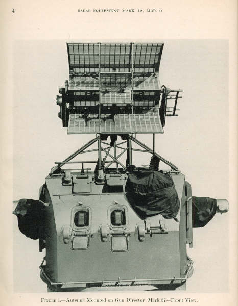
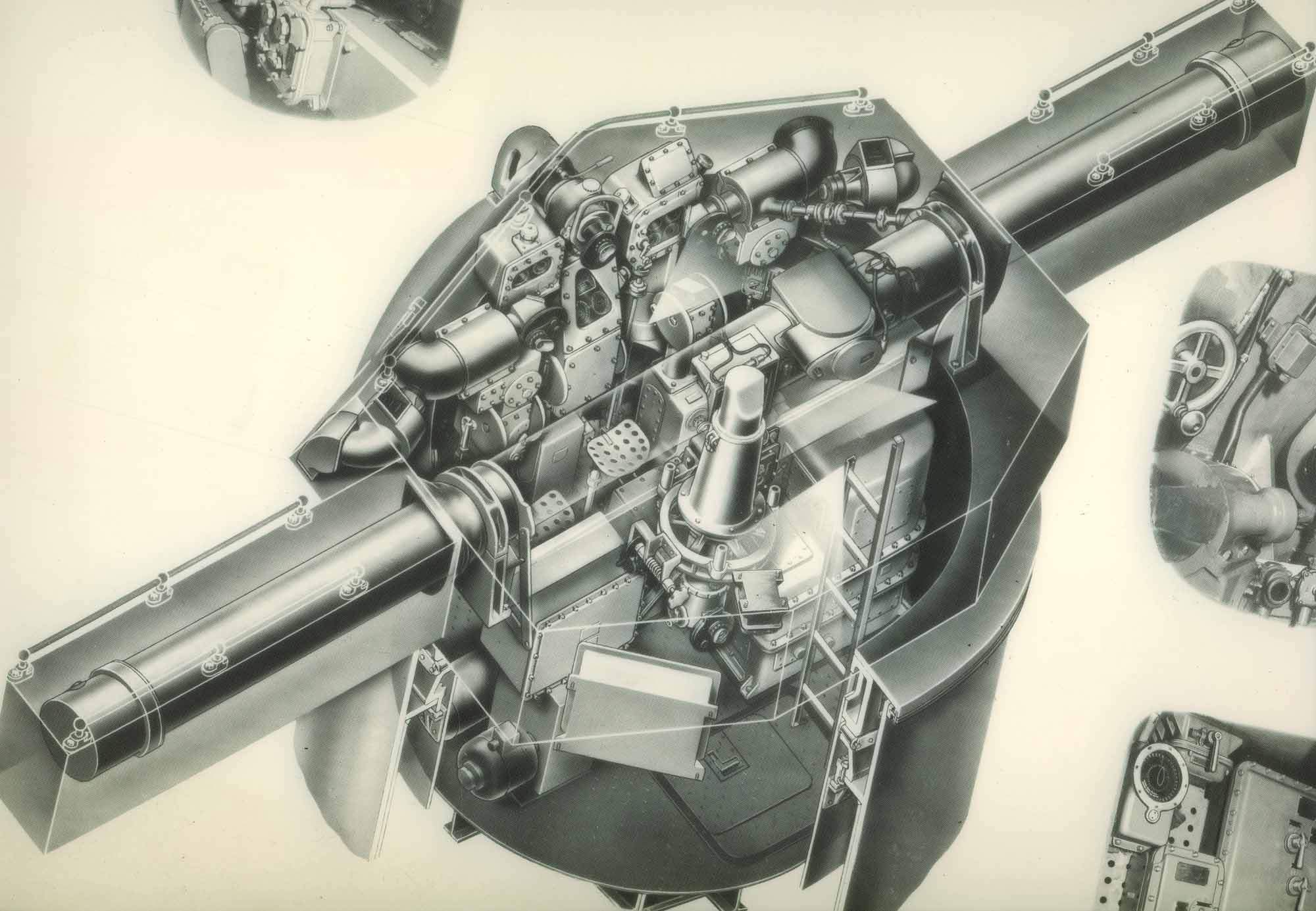
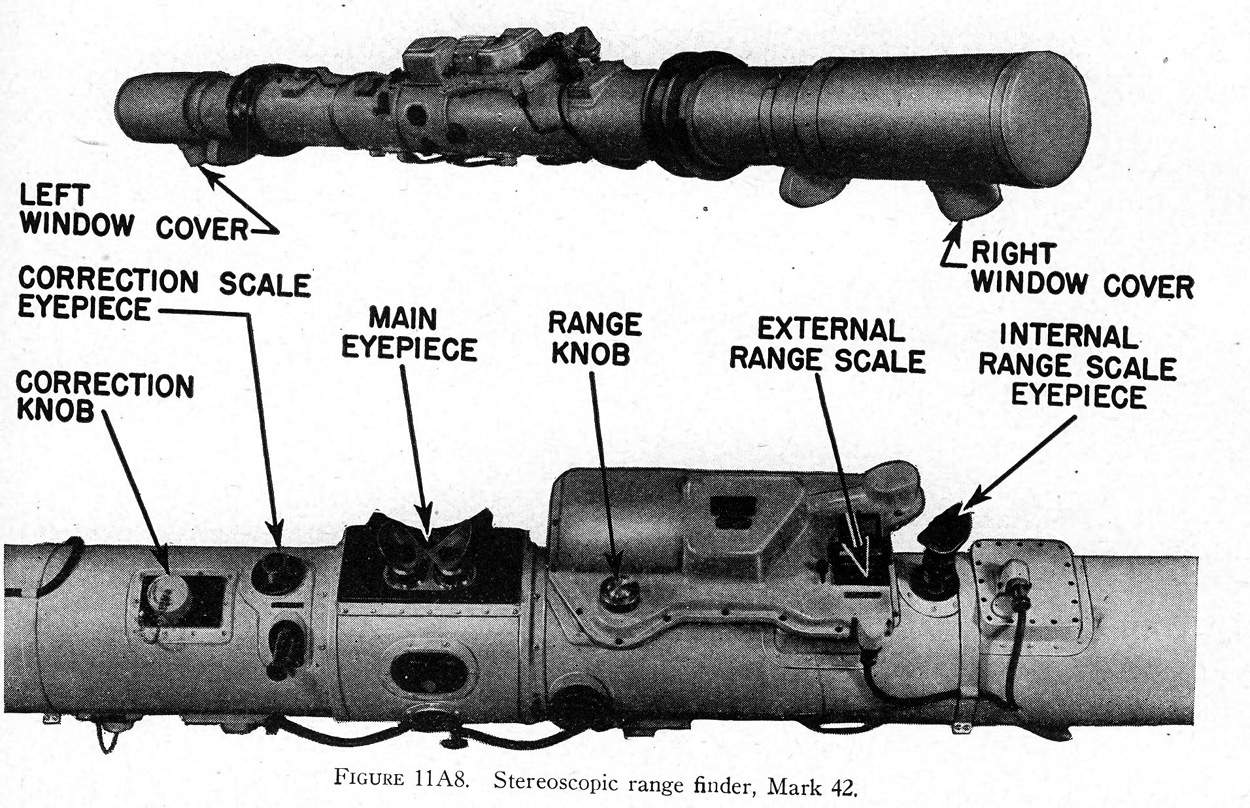
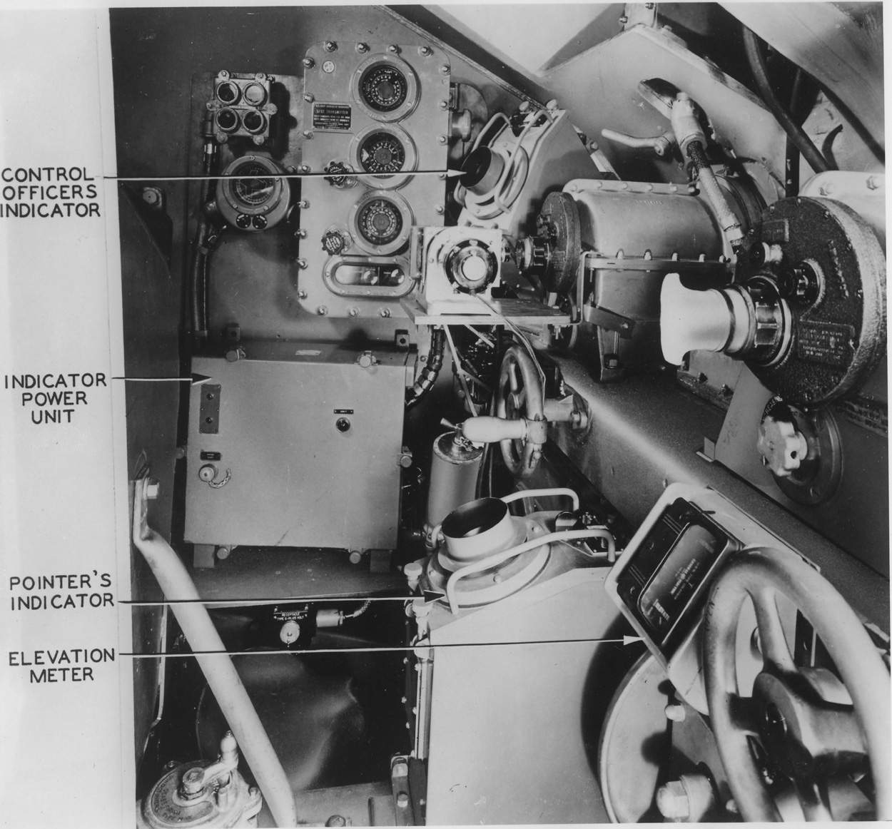
 | 150k | The director MK.37 was used to control the fire of the 5”/38 caliber dual purpose batteries against both aircraft and surface targets, to direct the fire of starshells for the illumination of surface targets and to position the searchlights. Provision was made for the following methods of fire: Continuous fire throughout the roll of the ship. Salvo fire at selected points of level. Salvo fire at selected points of cross-level. By suitable switching, means were provided for the control of fire simultaneously with control of starshells . Provision was also made, by means of arbitrary graduations of the parallax dials at the gun train indicator regulators, for the gun crews to offset their individual mounts in train for the purpose of firing starshell spreads. One complete director firing installation consisted of three major units, with their wiring connected to the indicator regulators of the guns and the searchlights. The major units were the director, the computer and the corresponding rangekeeper and stable element with its control panel. The director acted as the eyes of the system, being mounted as high as possible in the ship. It established the line of sight to the target and found the range, transmitted this information to the computer by synchro transmitters, along with the established target angle and speed of the target (by telephone) and rate of climb. The computer took this information, combined it with ballistics data incorporated within the computer and computed the fuze settings and deflection of the guns at the time of firing and the actual gun elevation and train orders. These were transmitted to the indicator regulators and the sights at the guns. The computer transmitted unit train parallax (calculated for 100 yard base length) to the gun train indicator regulator, which modified this quantity according to its horizontal distance from the ship’s horizontal reference point and added it to the gun train order. (The correction was zero when the guns were trained fore and aft). The computer continuously predicted the future position of the target at the moment of shell burst. The present range, elevation and train rates necessary to make these computations were used to position the director continuously in automatic control. If these rates were in error, the director sight would wander off the target. The pointer and trainer then put their sights back on the target, pressing their rate keys as they did so. This introduced a correction to their respective rates at the computer. The function of the stable element was to provide a horizontal plane of reference in which to stabilize the sights of the director, and to furnish selected points of level and cross-level for automatic salvo fire and continuous level and cross-level for hand firing. The stable element was orientated in train with respect to the controlling director. This was done mechanically from the computer. In addition, ships course was transmitted electrically to the stable element, so that, in conjunction with director sight train, it could be use to maintain the latitude correction weight on the gyro assembly in a true North and South direction. In order to prevent scattering fire it was necessary to take into account parallax, or the fact that no two directors or gun mounts will have exactly the same degree of train when directed at the same object except at very great ranges, or unless all three points lie in the same vertical plane. Since any director could control any or all of the five-inch mounts, it was necessary to have one central reference point on the ship for all guns and directors of the same class. (There is also parallax in elevation, but this was calculated in the computer for a fixed distance and entered into the elevation order there.) The following were parallax requirements: 1-The parallax reference in the vertical plane was the same as the trunnion heights of all five-inch guns. 2-Directors whose vertical axis did not coincide with the horizontal reference point transmitted bearing corrected for the difference between their actual position and the horizontal reference point. 3- Parallax was computed and transmitted separately by each computer for a unit value, which value was corrected by each gun train indicator-regulator and director train receiver-regulator for the actual distance of the specified gun or director from the parallax reference point. 4- No specific parallax value in the vertical plane was transmitted by the computer, but the gun elevation order contained a value due to the vertical parallax between the mean director positions and the mean gun trunnion height. 5- No correction in the vertical parallax because of difference in the horizontal base was required. 6- No horizontal parallax correction for gun mounts on either side of the ship’s centreline, when grouped to fire dead ahead or dead astern was required. 7- Horizontal parallax in all gun and director train indicator regulators was added by an automatic follow-up under all conditions of operation of the gun or director, when power for the parallax follow-up was available. In case of failure of the parallax follow-up current, such parallax was indicated and means were provided for introducing this correction by hand. 8- Calculation of parallax for the gun mounts and directors was done within the computer. The director firing installations were inter-connected for ease of handling and flexibility of control. Any director could take over the control of the entire battery or any part of it. Shown here is the Secondary Battery Plot of North Carolina (BB-55) in 1991. Any computer could be assigned to any director for the same battery, but each stable element could work only with the computer to which it was mechanically connected. The directors received target designation from the target designator system or other directors by means of synchro receivers in the train and elevation indicators. Provision was also made for the transmission of target bearing from the Mark 37 directors to the Main Battery switchboard. The following fire control instruments were located in each Mark 37 director aboard South Dakota (BB-57) in 1944: “FD” Radar range, elevation and train units. Pointer’s, trainer’s and control officer’s telescope. Director elevation indicator. Director train indicator. Searchlight corrector. Range spot transmitter. Rangefinder. Rangefinder carriage. Change of range receiver. Slewing sight. Roller path tilt corrector. Train receiver regulator. Cross-level receiver regulator. Target designation signal and selector switch. Parallax corrector (Directors 1 & 4 only) Portable firing key. Portable salvo signal contact maker. 17MC microphone. Battle telephones. Ship’s service telephone. Elevation receiver regulator. Range transmitter selector switch. Own ship’s course receiver. Cable twist indicator. Battle order and shell order transmitters. Elevation and deflection spot transmitters. Radar range reader and transmitter & Power transfer switch. All personnel had to know where all the above instruments were located in the director. Located in the base of the director were the power switches (three separate switches) for train, elevation and cross-level. Operation The personnel required normally to operate the director consisted of a crew of the following: Control Officer, Pointer, Trainer rangefinder operator, Radar operator, 5JP talker, JW talker (if one was assigned). All of the above personnel acted as lookouts in addition to their other duties. The primary duty of the Control Officer was to control the director, designate the targets and give the firing orders. He wore local JP phones. The Pointer manned the pointer’s handwheels, kept his horizontal crosswire on the target and made the necessary rate corrections when in full automatic. He wore local JP phones. The Trainer manned the trainer’s handwheels, kept his vertical crosswire on the target and made the necessary deflection rate corrections when in full automatic. The rangefinder operator manned the Mark 42 rangefinder, ranged and made spots. The radar operator took ranges with the “FD” radar, or, if the rangefinder was used for ranging, acted as range reader and “JQ” or “JW” talker in the case of transmission failure. The rangefinder operator also acted as a relief for the radar operator. The Control Officer operated the searchlights through the searchlight control transmitter, to sweep for targets when directed by Control. Noting the offsets on these instruments, he could inform the Control Officer of the relative location of the target. He also controlled the gun mounts firing starshells and made starshell spots. At General Quarters or in Condition Watches, the gun director was placed in the standby condition unless otherwise ordered. This means that it was ready to pick up any target that came in sight or within radar range and was ready to perform any function of which it was capable as soon as required. Close coordination between the director crew and the plotting room personnel was essential in the efficient operation of the director firing installation as whole. Close attention had to be paid to all warning plates located in the director. The usual steps to place the director in a condition of readiness were: The plotting room crew was informed of the nature of the expected target (air or surface) and the probable direction of approach and all that was going on or expected. The computer was placed in a standby condition. The illumination switches were turned on as necessary and set to “ON”-“TRANS” and then “BRIGHT” or “DIM” as required. The telescope crossline illumination was controlled by knobs located on the operator’s side of the optical boxes. The cross-level locking pin was withdrawn. The cross-level locking pin was thrown to ”ON”. The reset handwheel-switch was thrown to “ON” and the cross-level push button pressed. The director would then follow the stable element in cross-level. The train and elevation selector switches were thrown to “LOCAL” and the train and elevation power motors pushbuttons pressed “ON”. The director was now power driven in response to the pointer’s and trainer’s handwheels or in response to the Control Officer’s slewing sight. Operation of Mark 4 (“FD”) and Mark 12 radars. The Mk.4 radar was used for control of heavy A.A. batteries. It was effective against both air and surface targets but had certain limitations in both instances. Range accuracy of the “FD” was very good and constant for all ranges. Bearing accuracy was reasonably good but not as good as optical bearing (Same for elevation, except for targets between 50 and 1300 feet altitude which were within a range of 8000 yards.) Range discrimination was fairly good, being about 200-300 yds. between targets at approximately the same bearing. Bearing discrimination was not so good for closely grouped targets at approximately the same ranges. If two targets were at the same range and within about 15 degrees of the same bearing or less, the trainer could train to a point between the targets. Mark 4 radar was used in Mark 37 gun directors on battleships. This radar was the oldest type of radar used aboard capital ships at the time of writing (1944) and for that reason lacked many of the refinements of other radars developed largely during the war. It was more difficult to operate, more frequently subject to casualties. However, with a great deal of training for crews that operated and serviced it, it was a powerful weapon and had accounted for many Jap planes both at night and day. It was equally effective against light surface forces. The Mk.12 soon replaced the Mk.4 and had the same general characteristics, was better engineered and easier to operate due to improved methods of indication and also easier to service. All indicating units of the Mk.4 radar were located in the director. Transmitter and other units were usually located within 100 feet of the director in a space for one “engineer” of the equipment, just as important as a good operator for optimum performance. The radar operator in the director was captain of his four man team. He selected the target by his control and indicator and determined range by his range unit. The target then appeared for the trainer and pointer, two other members of the team, the fourth being the “engineer”. The trainer and pointer each had scopes with “matched pips” indication. By this method, the trainer trained the director to left or to right to maintain both pips the same size. When they were the same size, the director was on target in train. The same applies to the pointer for elevation. The utmost coordination between radar operator, director trainer and pointer was absolutely necessary for optimum performance of that radar. It was the paramount duty of the director officer to see that this coordination had been attained. The MK.4 radar could detect large planes as far as 80,000 yds., small planes at 50,00 yds. These ranges were frequently exceeded. The range accuracy was excellent, being constant for all ranges and errors normally did not exceed plus or minus 50-100 yds. Bearing and elevation accuracy were reasonable good and an experienced crew could stay on target without deviating more than plus or minus 1- to 2 degrees from optical bearing and elevation. At the time (1944) radar ranging was far superior to optical ranging but optical training and pointing superior to radar training and pointing. When visibility permitted, radar ranges were always used in cojunction with optical training and pointing for optimum performance. Mk.37 director control of 40 mm. quadruple mounts. At night it became desirable to control part of the heavy machine gun battery by a director equipped with radar. To accomplish this, six 40 mm quadruple mounts located near the Mk.37 directors aboard South Dakota had been wired in such a manner that they could be controlled through the searchlight correctors in the MK.37 directors. Quad. #4 sector1 and quad #3 sector 2 received synchro power through searchlight #3 and when searchlight #3 was put on Sky I, that director could then control these two quads. In a similar manner quad #1 sector 3, through searchlight #5, could be controlled by Sky III, quad 1 sector 4 through searchlight #4 could be controlled by Sky II and quad 2 sector 3 and quad 2 sector 4 through searchlight #6 could be controlled by Sky IV. Operation When the “night-time set-up” was ordered, a rotary selector switch on the battle telephone switchboard was put on “night-time set-up” and this segregated the six quads from their respective ”JY” circuit and paralleled them with the respective “JP” circuit. The searchlights were cut into their respective directors and the set-up was complete. Since the quads received no gun elevation order or gun train order, setting for the searchlight corrector was only approximate and the control officer had to watch the tracers to adjust the settings as necessary to bring the fire onto target. The quads had to be fired locally since there was no quad firing circuit aboard South Dakota through the Mk.37 director. Mk.51 director control of five-inch, 38-caliber mounts. General description: In the event that all MK.37 directors were out of commission, each 5”/38 mount could be controlled by a MK.51 director located near the mount. Since in this set-up the mount no longer received GEO, GTO or fuze setting from the computer, barrage fire had to be used with the desired fuze setting being set manually on the fuze setter in the mount. Operation To shift to this set-up, the mount captain in the mount had only to shift his selector switch to the MK.51 director and match pointers in “indicating”. There were two methods of establishing communications. One was to plug in a set of phones in the jackbox under the overhang of the mount. The preferred method was to make the necessary changes on the battle telephone switchboard in Plot. A bus was pulled to isolate the director from its JY circuit and then that director was jumped over to the JP circuit in the mount. The mount had to be fired locally and the fuzes set manually on the fuze setter in the mount. If there were no means of determining the range in order to determine the proper barrage fuze setting, 5 seconds were set and if the target got through that zone, they went to 1.8 seconds. The spotter at the director applied the spots to the sight to bring the fire on in deflection and elevation. | Text & USN photograph courtesy of Pieter Bakels. | |
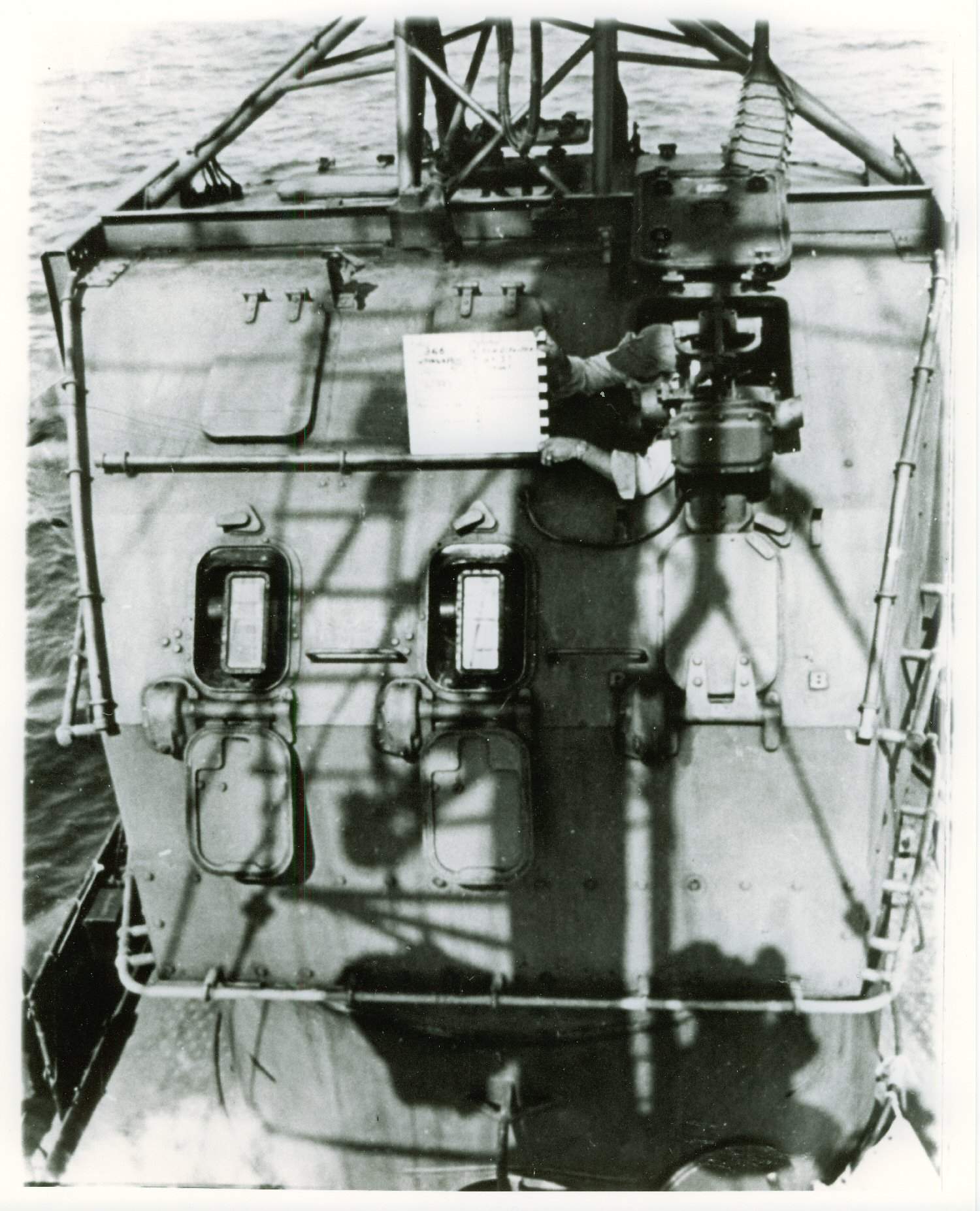
 | 54k | Mk.37 director aboard Massachusetts (BB-59) in October 1944. Please note the Mk.3 slewing sight on the director shield. In this earlier modification three telescopes had been fitted for the trainer, pointer and control officer. The function of the slewing sight was to bring the director telescopes on the rangefinder to bear on a new target in train and elevation in a minimum of time. The equipment was supported at the top of the director shield just forward of the control officer's hatch. The sighting unit mounted on the motor unit projected through an opening in the shield. The motor unit itself was secured within the director shield. After opening the hatch, the operator grasped the handles and slewed the sight bar relative to the director until the bar lined up with target and he closed the “SLEW” switch on the handle. As the introduced train and elevation relative to the director, two potentiometer’s movable arms were offset in the motor and caused the train and elevation follow-up motors in the motor unit to be energized. | Text & USN photograph courtesy of Pieter Bakels. | |
 | 32k | Mk.37 director aboard Massachusetts (BB-59) in October 1944, side view. Foot rails were fitted near the bottom of the shield and extended all around the director and hand rails to either side of the rangefinder slots, on the sloping front plates and roof plate. Note the spring-assisted port covers. Note the cockpit type hatch with a canvas buggy-top-type cover for quick closing and opening. | Text & USN photograph courtesy of Pieter Bakels. | |
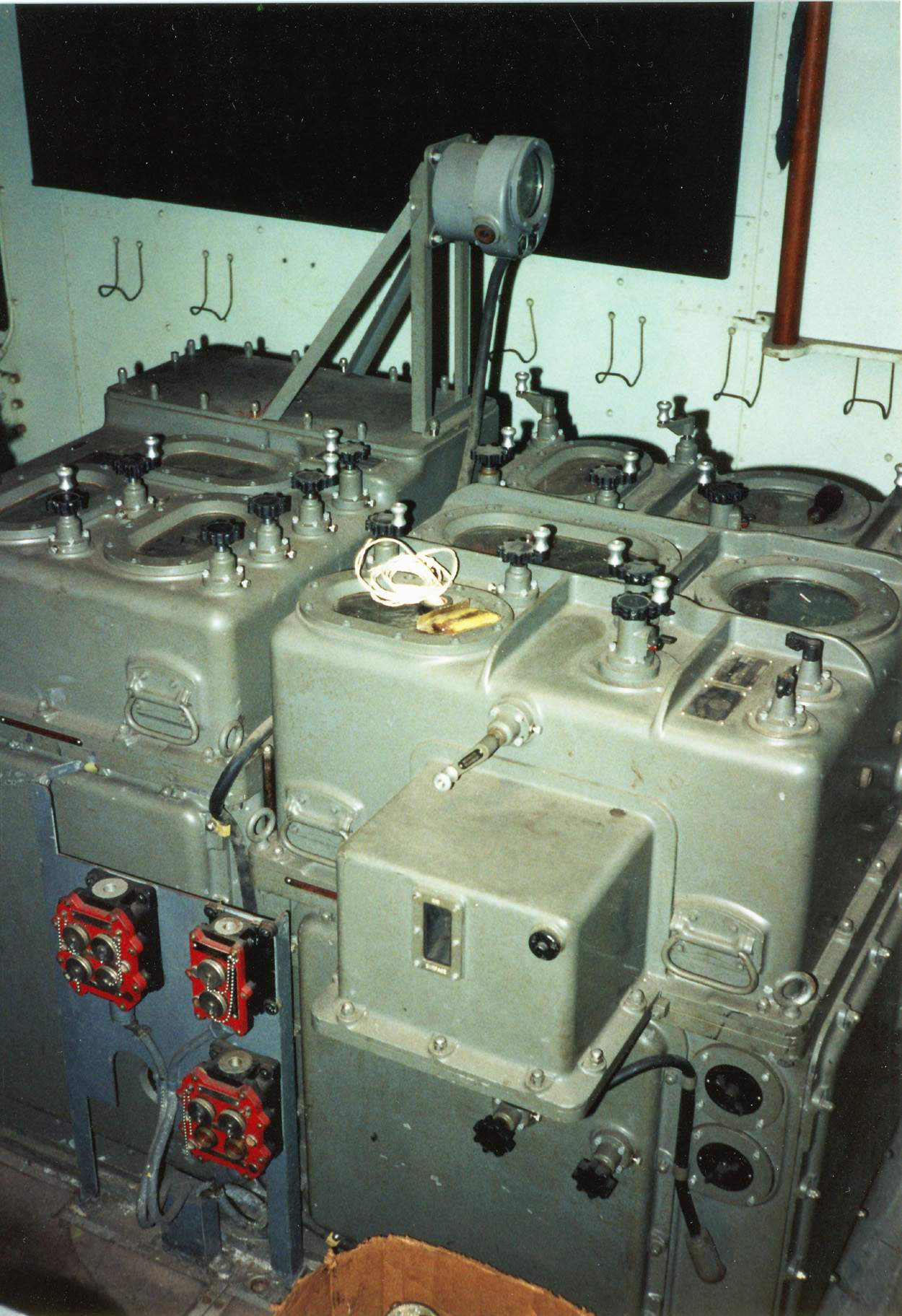
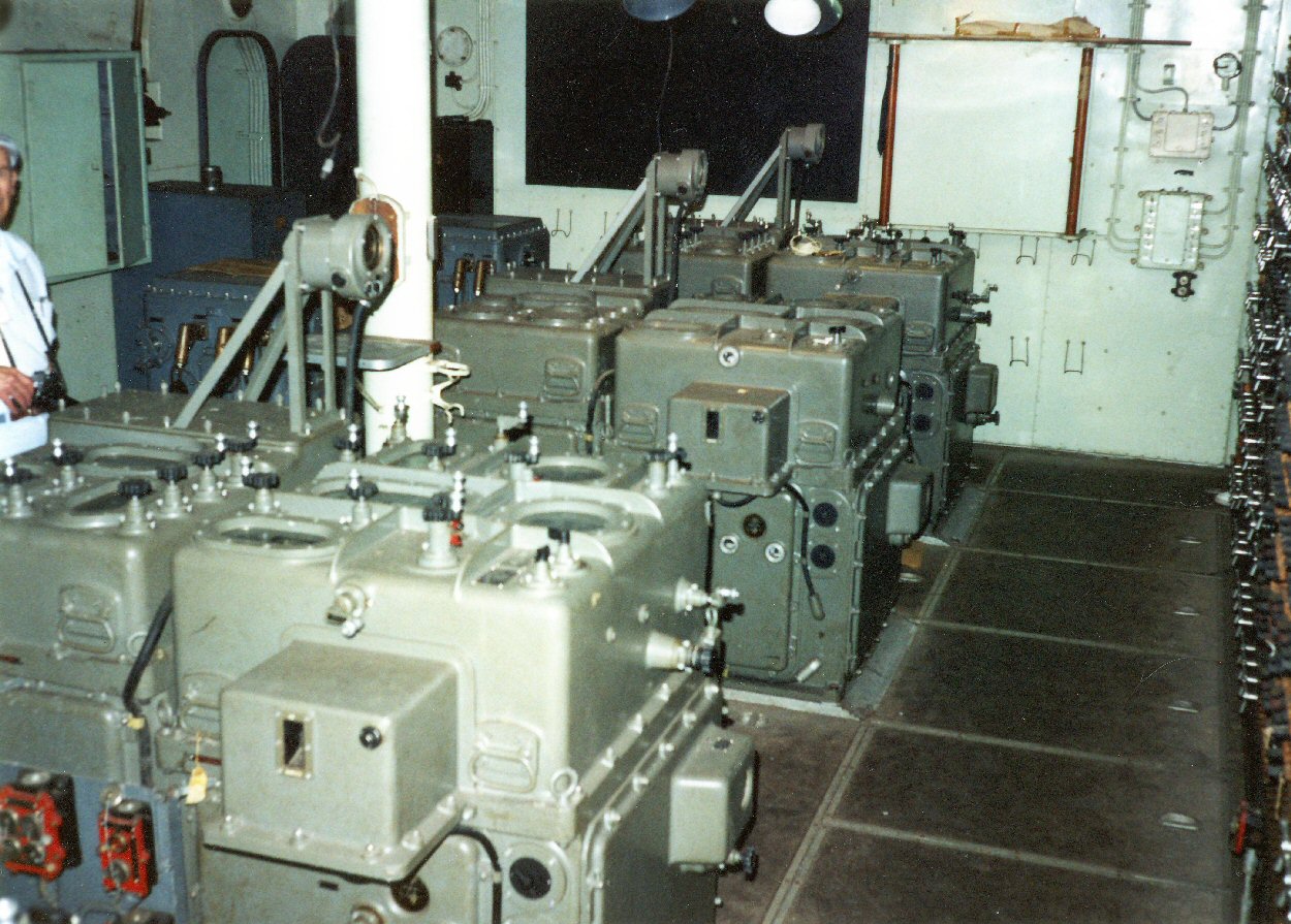
 | 52k |
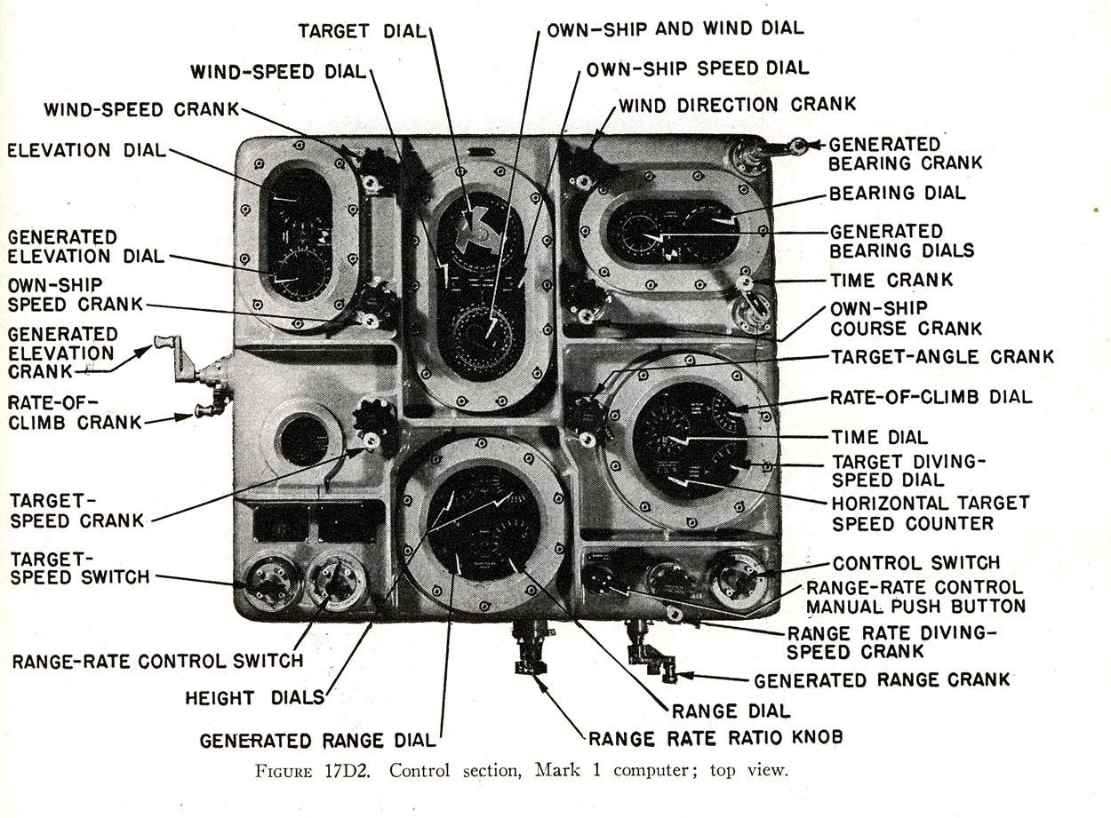
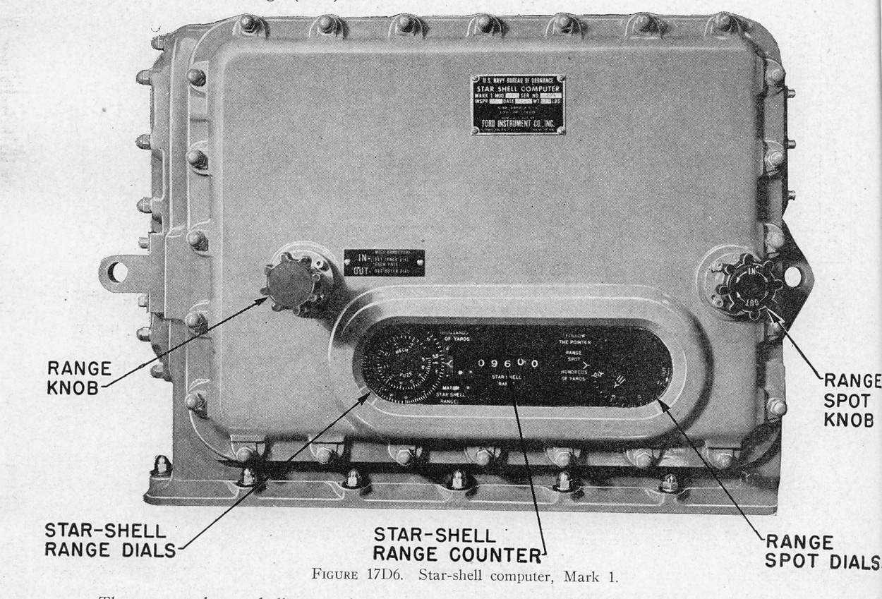
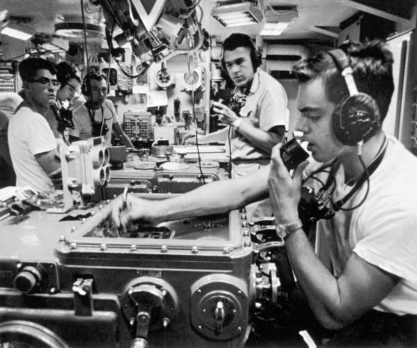
Mark I Mod. I Computer General Description The Mk.1 computer included the major portion of the controlling, computing and transmitting mechanism of the secondary battery fire control system. The instrument would compute, combine and transmit electrically the information necessary to permit the director line of sight to be maintained continuously on the target for anti-aircraft, surface or starshells . and to allow the guns to be pointed and trained and fuzes and sights set, continuously for surface, anti-aircraft or starshell fire. The computer generated bearing, elevation and range in accordance with known or estimated inputs as set on the instrument. A rate control system corrected the initial target set-up if any errors existed. For tracking targets with speeds greater than 40 knots, the computer was normally put in AUTO. Corrections to generated bearing and elevation were introduced by the director trainer and pointer and corrections to generated range by the computer operator. These corrections would produce through the rate control system the necessary changes to correct the target set-up. If for any reason the director pointer and/or trainer could not rate control, as was in the case of night air targets, the control switch was put on SEMI-AUTO. Changes to the set-up were introduced by the bearing rate controller and elevation rate controller at the computer by comparison of computed and observed quantities. Range rate control was the same as in AUTO. For targets with speeds less than 40 knots, it was not possible to rate control. The computer was put on SEMI-AUTO and the computer operator had to obtain a solution by adjusting target angle and target speed by hand until computed and observed quatities remained the same. There were certain problems such as bombardments and low flying torpedo aircraft where regular procedures had to be deviated from in order to obtain best results. These special procedures were covered in the Secondary Battery Plotting Room DOctober rine. Inputs to Computer and Methods of Introduction 1- Own ship’s course- Automatic or by hand. 2- Own ship’s speed- Automatic or by hand. 3- Target course (target angle) - by hand or by rate control. 4- Target speed- by hand or by rate control. 5- Wind direction- by hand. 6- Wind force- by hand. 7- Target rate of climb- by hand or by rate control. 8- Present range- match observed range from director by hand or by automatic. 9- Dead time- by hand. 10- Initial velocity- by hand. 11- Director elevation- automatic transmission from director, (automatic input to computer). 12- Level- mechanical from stable element. 13- Cross-level- mechanical from stable element. 14- Target bearing (relative) - automatic transmission from director. (Automatic input to computer). 15- Linear elevation rate correction- automatic from director or by hand at computer. 16- Linear deflection rate correction- automatic from director or by hand at computer. 17- Range rate correction- by hand at computer. 18- Elevation spot- automatic from director or by hand at computer. 19- Deflection spot-automatic from director or by hand at computer. 20- Range spot- automatic from director or by hand at the computer. Outputs, Method of Transmission and Destination 1- Gun train order- indicating and automatic, electrical to guns. 2- Gun elevation order- automatic and indicating, electrical to guns. 3- Fuze setting order- electrically or by phone to guns. 4- Sight deflection- electrical or by phone to guns. 5- Sight angle- electrical or by phone to guns. 6- Parallax for 100 yards. Horizontal base line- electrical to guns. 7- Relative target bearing to stable element- mechanical. 8- Computed increments of director train- electrical to director. 9- Computed increments of director elevation- electrical to director. 10- Computed increments of generated present range- electrical to director. Items Corrected for by the Computer The computer corrected the values used for laying the guns, setting fuzes and setting sights for: 1- Relative motion between target and own ship. 2- Roll and pitch of ship (converted into level and cross-level). 3- Loss of initial velocity. 4- Drift of projectile. 5- Curvature of the trajectory. 6- Dead time. 7- Surface wind across the line of fire. 8- Surface wind in the line of fire. 9- Effect of range and elevation on fuze setting order. 10- Range, elevation and deflection spots. 11- Parallax in train due to 100 yard horizontal base line. 12- Parallax due to 10 yard vertical base line. Discussion of Computer inputs The stable element measured level and cross-level and transmitted these functions to the computer mechanically. Cross-level was transmitted electrically to the director. Level was transmitted electrically from the computer to the director. At the director, level and cross-level were used to stabilize the rangefinder, radar antennae and three telescopes. The director was trained on the target and the line of sight was elevated by the pointer so that the horizontal cross wire was on the target. The relative train of the director measured target relative bearing uncorrected for deck tilt. This bearing was transmitted electrically to the computer where it was introduced automatically. The elevation above the line of sight above the reference plane included the target elevation and level. This value was transmitted electrically to the computer where it was introduced automatically. Present range was measured by the rangefinder and by radar. Present range was transmitted electrically to the computer where the computer attached zero readers to introduce range into the computer. True wind was reported by the aerographer and introduced into the computer by hand. Own ship’s course was transmitted electrically from the ship’s master gyro to the computer. If this method failed it could be set with a hand crank. Own ship’s speed was measured by a pito log and the change in speed was transmitted electrically to the computer where it was introduced automatically. It was necessary to set the correct speed initially by hand to insure proper synchronism. The initial velocity loss was obtained by adding algebraically the I.V. loss due to erosion, variation in velocity due to air density. This initial velocity loss was subtracted from 2600 f./s. (new gun initial velocity) and the present initial velocity was set on the computer by hand. The value of dead time was determined from the observation of loading drills and firings. This value of dead time was set on the computer by hand crank. The elevation, deflection or range spots could be applied either at the director or at the computer. All of the above inputs were known accurately and required no alteration from the known values to solve any problems. However, target course and speed and target rate of climb were not known accurately. Therefore, it was necessary to estimate these values and set them initially on the computer by hand. The director control officer estimated target angle and sent it to the computer crew by telephone where it was set into the computer by hand crank. This setting of target angle automatically set true target course into the computer. Target speed was estimated by the control officer who sent it to the computer by telephone. Target speed could be set by hand or by the target speed switch. Target rate of climb could be estimated by the director control officer who sent it to the computer by telephone and was set by hand. This was a very difficult quantity to estimate and was usually at zero at the start of any problem unless the target was known to definitely climbing or diving. Any range in this value was made by rate control corrections. Function of the Computer With the inputs of relative target bearing, target elevation, target course and speed, own ship’s course and speed, target rate of climb and observed range the computer solved that portion of the anti-aircraft problem which dealt with relative motion between own ship and target. The computer thus determined computed increments of director elevation, computed target bearings (relative) and computed increments of generated present range. These three functions represented the instantanuous changes of target bearing, elevation and range in accordance with the problem set on the computer. When the director was in AUTO and the computer was in AUTO or SEMI-AUTO, these quantities were used at the director to position the director in train, the telescopes, rangefinder and radar antennae in elevation and the radar in range. All of the above inputs were known accurately except target course, speed and rate of climb. If these were correct, the computed changes in elevation, relative bearing and range would be the same as the changes in the observed values and the director would stay on in elevation, train and range. If any of these values were not estimated correctly, the director would not stay on the target. This condition indicated that the problem as set on the computer was incorrect. This error would be in target course, speed or rate of climb. With the computer and director in AUTO the director pointer and trainer would bring the cross wires on the target with their handwheels. They closed their rate control keys while they were making this correction and the rate control section of the computer would correct the target course, speed and/or rate of climb as needed to correct these inputs and therefore solved the problem correctly. Any time the pointer’s or trainer’s handwheels were being turned in the above set-up, their respective solution indicators would be turning. When the rate control key was closed, a red flag showed on the computer. With the computer in SEMI-AUTO any motion of the trainer’s or pointer’s handwheels would indicate on the observed dials of the computer. This movement would cause a difference in readings between the observed and computed dials. The computer operators could either match the observed and computed readings without correcting the problem set-up (knobs in the OUT position), or they could match and correct the problem at the same time by rate controlling (knobs in the IN position). This rate controlling would correct the problem set-up. If the computer operator wanted to rate control in range, he pushed the range crank in while turning it and this corrected the problem by rate control. Outputs of the Computer Whenever the computer was running with the power and time motor on and the clutch from the stable element was in, the computer would be constantly determining gun train order. Gun elevation order, fuze setting order, sight angle, sight deflection and horizontal parallax correction for 100 yards base fire. These values were always computed in accordance with values set into the computer. All of these values were transmitted electrically to the guns to control the guns for firing. The values of gun train order, gun elevation order, fuze setting order, sight angle, sight deflection and horizontal parallax correction could be corrected for errors by spotting. The spots could either be applied at the computer by the computer crew who received them from the director by phone or they could be applied by the director personnel. In either case the values were automatically combined in the computer with their respective computer output. In addition to the above outputs the director transmitted electrically increments of computed elevation, bearing and range to the director as previously discussed. It also transmitted relative target bearing mechanically and own ship’s course electrically to the stable element. Stable Element Mark VI / General Description The instruments, four in number, were located in the Secondary Battery Plotting Room, one adjacent to each computer. They transmitted to the directors by means of synchro generators a value of cross-level. Values of level and cross-level were transmitted mechanically to the adjacent computer. The stable element also provided means for: 1- Automatic firing in selected level. 2- Automatic firing in selected cross-level. 3- Hand firing in level. 4- Hand firing in cross-level. The Inputs to Each Stable Element Consist of: 1- Own ship’s course- electrically at single speed from gyro compass. 2- Target bearing (director train) - mechanically to computer. The Outputs of Each Stable Element Consist of: 1- Cross-level (selected or continuous) - mechanically to the computer. 2- Level (selected or continuous) - mechanically to the computer. 3- Cross-level- electrically to the computer. 4- Level plus a function of cross-level (continuous) - mechanically to computer. In addition, the electrical inputs to the Stable Element Control-panels were as follows: 1- Own ship’s course at 36 speed. 2- Own ship’s course at 1 speed. The function of the Stable Element was to provide the means by which the lines of sight of the optics and the rangefinder could be automatically positioned to eliminate the effects of the roll and pitch of the ship and to permit firing continuously or at any point of the roll or pitch of the ship. Specifically, the Stable Element measured and transmitted values of level and cross-level angle to the computer and the director and provided means for firing the guns. Functional Description The Stable Element consisted of a gyro wheel mounted in a gimbal system which gave it three degrees of freedom. Briefly it was a restricted gyro, i.e., it was restricted to the vertical plane. This was accomplished by means of a gravity flow of mercury located in two connected tanks which were located on opposite sides of the gyro case. When the spinning axis of the gyro was not in the vertical, mercury flowed to the low tank thereby applying a precessional force to that side. Precession was 90 degrees from the point of applied force but this was taken care of by a continuous rotation of the gimbal system at 18 r.p.m. which caused the precessional force to lag the point of application by 90 degrees thereby causing the gyro to precess toward the gimbal. Mounted on top of the gyro case was a latitude motor which was connected to the ship’s gyro compass. This motor carried a latitude weight and maintained it in a north-south direction. This weight applied a precessional force to correct the gyro for apparent rotation of the gyro due to rotation of the earth. Mounted above the latitude motor was an alternating current magnet. The magnetic field around this magnet induced a small voltage in a pair of estatically wound coils that roll and pitch with the ship. This signal voltage was applied to an amplifier circuit which controlled a grid controlled rectifier (thyratron circuit). These thyratron tubes rectified the A.C. power to control the level and cross-level follow-up motors. These motors were geared to the support which carried the estatically wound coils thereby driving them back to a neutral position. This in effect measured the level and cross-level angles as indicated by the respective dials on top of the instrument. The inputs of ship’s course and ship’s speed to the control panels actuated a cutout device to stop the flow of mercury when the ship was making large turns or changed speed. This was necessary because any disturbance in the natural flow of mercury would tend to displace the gyro from the vertical rather than to right it. Operation Normally the stable elements were used in automatic with continuous fire and no crew was necessary. For salvo fire against surface targets the firing circuits were controlled at the stable element and a firing pointer was provided equipped with a stopwatch and fired by the hand firing key at designated intervals. At night or during conditions of poor visibility or for reasons under which the director pointer had no point of aim on surface targets and for firing starshells, level was controlled at the stable element. This was done by putting the synchronize elevation knob on the computer in the out position after setting observed elevation on zero 9 with knob in the center position) and setting dip range. Firing circuits were normally controlled by the director in this setup. For all types of air targets the stable element was operated in full automatic with the director in control of elevation and firing circuits. If it was necessary to shift to manual operation, a leveler and cross-leveler were required. Switchboards There were two mount switchboards- one for the starboard mounts and one for the port mounts. By means of the switches on these boards, the mounts were shifted among the sky directors as desired. The normal method of shifting a mount was to “lock it” t the switchboard. This was done as a precautionary measure and made it necessary for the mount captain to shift his mount out of automatic (if his mount was in automatic at the time of the shift), match pointers, and shift back to automatic before the mount would again move in automatic. There also was a “fast method” of shifting the mounts in which the mount was not locked. This method could be ordered by Air Defense in cases of extreme emergency and then only when the directors involved were on the same or almost the same bearing and elevation. MC Switchboards This was the power supply board for the various transmitters. Also the desired set-up for the firing circuits and 17MC was made at this board. Director-Computer Switchboard Here the computers were cut in to the directors. Any combination could be set up, but the normal set-up was for each computer to go to the correspondingly numbered director. Stable Element Switchboard This switchboard controlled the stable elements. The thyratron tubes for the follow-up system were located here and the switches on this board started the gyros (or stopped them as the case might be). Battle Telephone switchboard This switchboard controlled communication for both the secondary battery and the machine guns. Crewman wearing sound-powered headphones. in Main Battery Plot obtain firing solutions from the ship's firecontrol computers. |
Text & photos submitted by Pieter Bakels. | |
| Back To US Battleship Construction Index | Back To The Main Photo Index | Back To The Battleship Photo Index Page |
This page is created by Pieter Bakels and Michael Mohl & maintained by Michael Mohl
All Pages © 1996 - 2025, by Paul R. Yarnall NavSource Naval History. All Rights Reserved.