| Click On Image For Full Size Image |
Size | Image Description | Contributed By And/Or Copyright |
|
|---|---|---|---|---|
 | 2.5mk |
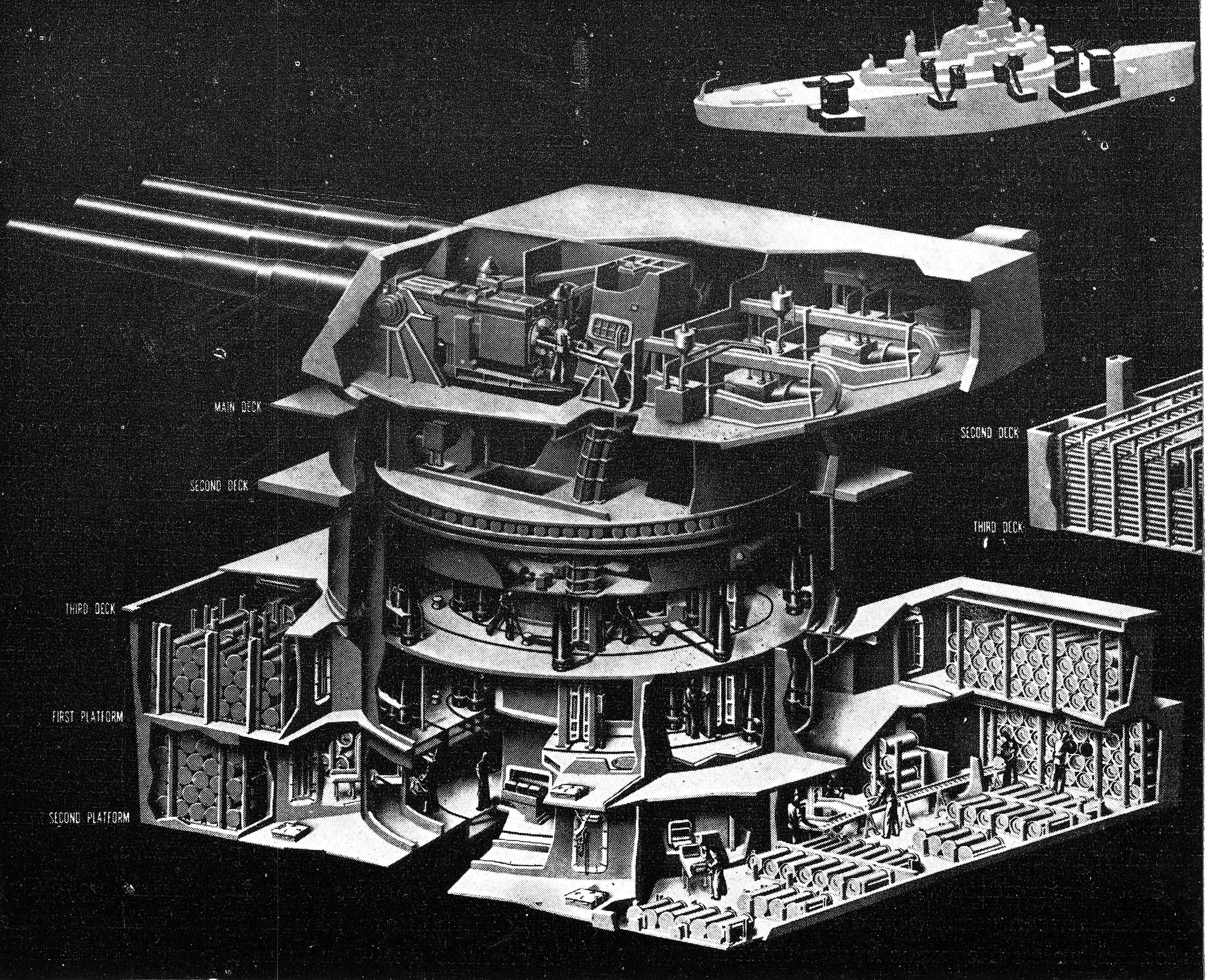
MAIN BATTERY The Main Battery is the reason-for-being of this ship. The responsibility of officers charged with running the battery is great and should be lived up to at all times. Normally the battery would be employed against enemy capital ships. Should such targets not be present the most dangerous targets in the vicinity would be taken under fire. A ship of this type also plays an important part in shore bombardments. Normally our function would be to take part in the preliminary phases of a landing operation bombarding from long ranges and closing in as necessary to cover our objectives. The Gunnery Officer in the Fire Control Tower will normally be in direct control of the battery. During shore bombardments the Gunnery Officer usually delegates this authority to Spot One, the control officer in Main Battery Director One. Should casualties occur in a surface action the sequence of officers controlling the battery will be: (a) Gunnery Officer. (b) Spot One. (c) Spot Three (if an officer is present). (e) Turret Officer of Turret Two. (f) Control Officer of an available Secondary Battery Director. During daylight normally slow fire will be used until the first spot has been applied, at which time the control officer will order salvo fire, rapid fire, or continuous fire. If the target is maneuvering radically, the order may be given to open with continuous fire. At night the same procedure will be followed except that continuous and rapid fire normally should not be used in order to reduce the blinding effects of unexpected muzzle flashes. Normal Set-Up Normally the battery will be in primary fire, with Director One controlling train through Range-keeper One and Director Four controlling level, cross-level, and firing circuits. Director Two will control train through Range-keeper Two, with Director Five controlling level and cross-level into that range-keeper. Range-keeper One will control the battery. Director Two will normally pick up the next most likely target to be taken under fire, and Director Three will be free to search for new targets. As the fire control switchboard is capable of many combination's other arrangements of control may be set up as ordered. Auxiliary Control Auxiliary control is such that the turrets are trained and elevated in accordance with gun train and elevation orders from either the computer in the Fire Control Tower (with Trunnion-tilt Corrector) or the computer in Turret Two. Auxiliary control goes through the auxiliary fire control switchboard in Turret Two which is completely isolated from the switchboard in the Plotting Room. This is a secondary means of control and will normally be used when all other methods of primary are out. TURRET PROTECTION The rotating turret structure is protected by heavy armor plate on the gun house and from the shelf plate to the 2nd Deck is enclosed within a cylindrical barbette of proportionally thick plate. Belt armor, deck plating and heavy circular foundation plates constitute protection for the space below. Thus -enclosed the entire space is water, gas and weather sealed with special provision for adequate ventilation of all subdivisions and for maintenance of air ~pressure level throughout. Semi-automatic sprinkling facilities are provided for gun compartments, hoist trunks and projectile stowage. Compressed air, power supply services and communication leads are brought in conventionally through a central column trunk and column pivot casting. TURRET ARRANGEMENT The interior of the turret is sub-divided into compartments as follows: The gun chambers (shown here is the breech of the chamber), turret officers booth, sight stations, bull gear compartments, and the ventilation unit compartments are all within the weldment, above the pan plate. Below the pan plate is the electric deck compartment including the pinion gear compartment at the front end. Below the electric deck are two shell handling levels, the upper and lower projectile flats. Below the shell, flats is the powder handling room into which the lower entry doors to the powder hoists open. Extending from the under side of the electric deck to the wiring trunk below the powder handling room on the center-line of the turret is a central column wiring tube, enclosing the main turret wiring and H. P. air piping. Above the pan plate of the weldment, the turret is divided into six gas and flame tight compartments. A transverse bulkhead subdivides the Booth from the three gun chambers. Longitudinal box girders, together with longitudinal divisional bulkheads, running between the transverse Booth bulkhead and the turret face plate above and in line with the box girders of the turret weldment, to the turret roof, divide, the gun chambers, one from another, into three gas and flame-tight compartments. The outboard divisional bulkheads, together with a small additional transverse bulkhead located just forward of the Booth transverse bulkhead, form the gas and flame-tight sight stations in the wings above the shelf plate. The electric deck is subdivided by non-tight bulkheads running in line with the box girders of the weldment above. The projectile flats below the electric deck are divided by a non-tight circular bulkhead into handling and machinery spaces. The lower flat is separated from the powder handling room by a flame-tight compartment. All revolving portions of Turrets, One, Two and. Three are similar. In Turret Two due to the exceptional depth (This photo is of the Arizona (BB-39) in 1938)of the powder handling room, an additional projectile storage platform which is fixed has been added and rings the upper part of the compartment. Main access to the turrets is by way of two A-B hatches located in the turret overhangs opening into the Booth. Additional access is provided by means of ammunition trunks opening through armored doors into the powder circle which surrounds the powder handling room. TURRET OFFICERS BOOTH The turret officers booth is located in the rear overhang of the turret above the shelf plate, and to the rear of a transverse gas and flame-tight bulkhead. In this compartment are located the rammers, the rammer power units, the range finder,, periscopes, sprinkling tanks, vent sets, remote control switches and valves for sprinkling systems, and fire control switchboards. The entrance doors to gun chambers, and powder hoist operators stations are located in the transverse bulkhead. Control switchboard and microphone units for turret amplifying system are located in the Booth adjacent to the ready light panel. The turret ready light switch, ready light panel, synchro light panel, firing cutout camlight panel are all located on the transverse bulkhead just to the right of the access door to the center gun. Here the turret officer takes his station. Shown here is the entrance doors rangefinder in Turret Officer's Booth. GAS AND FLAME SEALS Box girders Extending between the pan plate to approximately the centerline of the trunnions as integral parts of the gun weldment, segregate the weldment into three gas and flame-tight compartments, longitudinally. Longitudinal bulkheads between the tops of the box girders and the turret roof plates, subdivide the three gun chambers from each other and form a tight subdivision between the wing gun chambers and the sight stations to the front of the transverse Booth bulkhead. In way of the guns, gas and flame-tightness is assured by the gun slide shield plates, which ride between longitudinal cheek plates extending to the turret face plate. The edges of the slide shield plate are fitted with spring bar, pressure type gas and flame shields. Under the guns, 3" S.T.S. splinter protection plates carry the lower edge of the cheek plates in grooves and provide a wiping surface for the lower gas and flame shield, fitted to the slide shield plate. Heavy leather bucklers cover the gun ports. They exclude green seas and help exclude toxic gasses and assist in maintaining air pressure from within. All pipes, cables, operating rods, etc., penetrating the gas and flame-tight bulkheads above the pan plate are fitted with stuffing boxes of approved type or are otherwise protected to assure gas and flame-tightness within the gun chambers. Access doors and hatches located in gas-tight platforms or bulkheads are fitted with asbestos gaskets with suitable dogs for tightness. A special gas seal and watershed is provided in way of the shelf plate and the barbette armor belt, protecting the turret interior from external gasses and green seas. This seal is formed by a trough section fitted to the top edge of the barbette and a tongue section fitted to the revolving turret. The trough is packed full of grease, in which the tongue rides as the turret revolves. The trough is replenished with grease as required, through fittings located in the seal. The seal is pressed from light gauge C.R.S. and attached by tap bolts to armor and turret. CENTERING PINS The centering pins are two in number, located just to the front of the booth bulkhead on the shelf plate, one each in the right and left gun chambers. The centering pins lock the turret, on the center-line of the ship, to the heavy barbette armor. The pins are operated by screw thread, by means of a special wrench, stowed on an adjacent bulkhead. The control of the centering pin operating gear is located on a ramp forming a vent trunk outboard of the outboard gun girder. ROLLER PATH Lower Track The lower track is supported on a conical S.T.S. foundation bulkhead. They are of laminated construction. The track proper is of steel castings, thermite welded, to form a hollow ring. The upper portion of the track is machined out, to support a forged steel roller race, of sufficient Brinell hardness capable of withstanding the roller pressures. Each track roller race is fitted with six portable blocks, for use in the removal of rollers. The upper surface of the lower roller race is slightly beveled to suit taper of the rollers. Upper Track The upper track is composed of two forged segments, welded together at the butts, forming a solid ring. The upper track is welded to the pan plate on the large periphery and bolted by a flange to the pan on the small periphery. Keys are fitted in certain portions of the upper track and are welded into the pan plate to take shear pressures under gun fire. The faces and edges of the upper and lower roller races are finished machined to close tolerances. Turret Rollers The turret rollers are 60 in number, spaced radially between the upper and lower roller tracks. The rollers are forgings, hollow bored. A thick flange on each end of the rollers hold the tracks. The rollers ride in a circular carriage formed of roller plates. The carriage spaces the rollers by means of axial bolts supported in bearings in the rollers. The carriages are supported by spacers bolted between the vertical side plates at intervals. The carriages assure the relative position of the rollers during turret train. TURRET VENTILATION Each turret is ventilated by eight supply fans, of axial flow type as follows, with natural exhaust: 3000 CFM supply to Booth. 4000 CFM supply to right gun chamber. 4000 CFM supply to left gun chamber. 4000 CFM supply to center gun chamber. 4000 CFM supply to left sight station and shell flat. 4000 CFM supply to right sight station and shell flat. 4000 CFM supply to right electric deck. 4000 CFM supply to left electric deck. Automatic shutters are fitted between supply fans and gun chambers. Manually operated A.T. covers are fitted on supply and natural exhaust in turret officer's booth. They should be closed when fan is shut down. Natural exhaust from each 3-gun chamber is fitted with automatic shutters on shelf plate. Natural exhaust from pan plate level is through automatic shutters at shelf. The natural exhaust from the electric deck and shell flats is up between the barbette and the weldment circular bulkhead, through automatic shutters in the shelf plate. With the gun port bucklers in place the turret ventilation systems are capable of maintaining in the gun chambers an air pressure of one (1) inch of water. The automatic supply shutters are arranged to close and the automatic exhaust shutters to open when this pressure is exceeded in the space which they serve. All heating within turrets is by electric heaters. POWDER HANDLING ROOM AND MAGAZINE VENTILATION Each turret powder handling room has its own 4000 CFM, axial flow type supply and exhaust fans. In this ventilation circuit is a by-pass connection in which is inserted a cooling coil for use when material condition ZEBRA is set and all access to outside air is closed. When used this cooling system is designed to maintain an effective temperature of 90° F. in the powder handling rooms. The supply air duct for all powder handling rooms systems is carried from main deck down to second platform where it enters the powder circle around the handling room. There the duct is split into two sections; one supplying the powder circle and handling room and the other, through branches, the various powder magazines on the first and second platforms. The exhaust duct is likewise split into two sections in the powder circle. The terminals in the handling rooms and powder circles are fitted with automatic shutters. Where the branches enter the magazines from the powder circle double flap valves are fitted. On the third deck there is a by-pass connection between the supply and exhaust duct. In this bypass, connection is located a cooling coil and a shut-off valve. In the main supply and exhaust ducts there are shut-off valves on the weather side of the by-pass connections, directly under the third deck. For normal cruising the weather closures are open. The shut-off valve in the by-pass is closed, and the cooling system is idle. The dampers in the branches to the magazines are closed. The full volume of air is directed to the two terminals supplying the handling room. Both supply and exhaust fans are in operation during this condition. For General Quarters the exhaust fan is stopped and the weather closures are secured. The shut-off valve in the ducts on the weather side of the by-pass connection are closed and the valve in the by-pass is opened. The cooling plant is placed in operation. The purpose of the magazine blowouts is to replenish' oxygen and prevent ether fumes and the C02 to build up above 3%. Dampers in the branches are to remain closed until it becomes necessary to blow-out. When this is necessary, on orders only from the turret officer who must first obtain permission from the First Lieutenant, the weather supply closures are opened as are also the 71/g" gate valves located in the supply duct immediately below the 2nd Deck. The by-pass valve located on the 3rd Deck is to be closed. The dampers at the splits are to be set to direct the air to the magazines. The weather supply closure should be manned in these circumstances for immediate closing if and when necessary. Handling room personnel will operate the double flap valves and at the same time the magazine personnel will manually hold open the check valves in the air escape. The latter should be kept open as long as air is being supplied to the magazine. Magazine personnel are responsible for seeing the check valve closed when it is not used to ventilate the magazine. In addition to the blow-out system each, magazine has cooling coils installed on the overhead to maintain magazine temperatures at 90° F. Temperature conditions are thermostatically controlled. ' TURRET SPRINKLING SYSTEMS There are three sprinkling systems within the turret, the 16" projectile sprinkling system, the 16" powder tray transfer sprinkling system, and the hydraulically operated turret sprinkling system. The 16" projectile system is provided to sprinkle the projectiles stowed on the shell flats. Sprinkling rings of 2" pipe are provided on each shell platform within the barbettes. Water to these rings is supplied directly from the firemain and is controlled by a manually and electrically operated control valve located in the powder circle adjacent to the powder handling room of each turret. Electric operation of the valve is from the Booth, upper shell flat, intermediate shell flat (Turret Two only), and lower shell flat. Manual operation is at the valve in the powder circle. The 16" Powder tray transfer system is installed for sprinkling powder in transfer from the magazines to the powder handling room. The water supply to this system is direct from the firemain and is controlled by a manually and electrically operated control valve located in the powder circle adjacent to each 16" powder handling room. The electric control stations for this system are located as follows : 1-16" Powder Handling Room (Turret One only) 1-Powder Circle (Turret One only) 2-16" Powder Handling Room (Turrets Two and Three only) 2-Powder Circle (Turrets Two and Three only) 1-Turret overhang 1-Booth Cut-out valves are provided in each firemain branch to the projectile and powder transfer tray sprinkling systems and are locked open. A series of indicating lights at the control stations indicate when the control valve is open, moving, or closed. The hydraulically operated turret sprinkling system is provided to sprinkle the gun breeches, projectile hoists and loading trays and powder hoists in the handling room. The water supply is from the firemain via a portable hose. The hose is connected to the hose valve of the firemain in the handling room and the hose valve controlling the riser to the turret. When using water from the firemain (300 gallons of fresh water normally kept in relay tanks in Booth for use in this system) both of these valves should be opened and left open until all firing has ceased. Magazine sprinkling The magazines of the ship are divided into ten groups for the purpose of sprinkling. Each group is supplied by a separate connection taken off from the firemain at a convenient location and controlled by a group control valve. The group control valves are operated electrically from one of the two remote control stations. Groups 1, 2, 3, 4, 7 and 8 are operated from Damage Control and groups 5, 6, 9 and 10 are operated from Sprinkling Aft located in Compartment C-303L (P). Turret One's magazines constitute Groups 1 and 2; Turret Two's, Groups 3 and 4 and Turret Three's Groups 5 and 6. Handwheels are provided in the powder handling room of each turret for local operation. A series of indicating lights at the control stations indicate that power is available and whether the valve is open, moving or closed. In addition to the group control valve each magazine is provided with a cut-out valve of the stop-lift-check type. These valves should be kept locked in the check position. There is no provision in this vessel for flooding magazines directly from the sea. Magazines can be flooded in forty minutes through the sprinkling system. After doing any painting on any sprinkling pipe it should be checked to insure that all perforations in the pipe are clear to allow a free flow of water. POWER SUPPLY In order to understand the limitations of the Main Battery Power Supply System it is necessary to know a little about the ships Distribution System. This ship has seven 1000 k. w. turbo generators and two 200 k. w. diesel generators. These generators supply 440 volt, 3 phase supply to the four Distribution Boards and the two emergency Distribution boards. These generators are located as follows: Nos. 1 and 2 in No. 1 Machinery Space. Nos. 3 and 4 in No. 2 Machinery Space. Nos. 5 and 6 in No. 3 Machinery Space. No. 7 in No. 4 Machinery Space. Forward diesel generator in the evaporator room. After diesel generator in the after diesel generator room. The distribution boards are located as follows : No. l in Forward Distribution Room. No. 2 in No. 2 Machinery Space. No. 3 in No. 3 Machinery Space. No. 4 in After Distribution Room. Forward emergency board in the evaporators. After emergency board in the After Diesel Room. During normal battle condition the ships distribution boards are unitized. That is, each board is supplied by its own generators and is entirely independent of the other boards. During this condition No. 1 and 2 generators are paralleled on No. 1 board, No. 3 and 4 generators are paralleled on No. 2 board, No. 5 and 6 generators are paralleled on No. 3 board, and No. 7 generator supplies No. 4 board. This is the normal battle set-up. In an emergency, however, many different combination's are possible. Turret One receives its normal supply from No. 1 board, its alternate supply from No. 2 board. Turret Two receives its normal supply from No. 2 board, its alternate supply from No. 1 board. As a matter of information it may be noted that Turret Two receives a 117 volt emergency supply from the Forward Diesel Board for its auxiliary fire control switchboard. Turret Three receives its normal supply from No. 3 board, its alternate supply from No. 4 board. It is interesting to note the weakness in the alternate supply to Turret Three since No. 4 board has only one generator supplying it during normal battle condition. If for any reason it becomes necessary to use the alternate supply to Turret Three, No. 4 board would be immediately paralleled with one of the other boards. This is a matter of routine with the personnel manning the distribution boards. In as far as possible the normal and alternate feeder to a turret take separate courses, one on the starboard side of the ship and the other on the port. Each feeder is made up of four three-conductor, heat and flame proof, four hundred thousand circular mill cable. In other words each feeder has a cross sectional area of sixteen thousand circular mills. The feeders terminate at feeder boxes located at the base of the center column of the turret. From the feeder boxes, flexible cable of the same size as the armored cable runs through conduit into the center column of the turret. NOTE : An alteration has been approved to remove the conduit and to make a watertight joint both where the cable leaves the feeder boxes and where it enters the column. The flexible cable is run up the center column, and comes out of the center column into the upper shell deck. The reason for using flexible cable in this part of the run is of course to take care of the continuous movement of the cable where it runs from the stationary to the movable part of the turret. On the upper shell deck the feeder runs into a bus transfer panel. From this bus transfer panel sub-feeders run to the various power panels in the turret. It should be noted that the sub-feeders run directly to the various power panels without being protected by AQB breakers. NOTE: A ShipAlt authorizing correction of this defect at next period of navy yard availability is aboard ship. The marking of the panels and the equipment supplied by them is indicated in the following. Turret Three T3-1 Bus transfer panel. T3-2 Power panel, training gear. Training gear motor. Training gear lubrication pump. T3-3 Power panel, No. 1 gun equipment. Projectile hoist. Rammer. Elevating gear. Powder Hoist. Projectile hoist cradle. T3-4 Power panel, No. 2 gun equipment. Same as panel T3-3. T3-5 Power panel, No. 2 gun equipment. Same as panel T3-3. TS-C, Power panel, Miscellaneous equipment. Lower par-buckling gear. Lower projectile ring. Vent system T3-R. Vent system T3-R. Vent system T3-L. Vent system T3-L. Upper par-buckling gear. Upper projectile ring. Vent system right gun. Vent system left gun. Vent system center gun. Circuit RA transformer. 40mm Quad No. 15. The panels for Turret One and Two are the same as for Turret Three except that they are marked T-1 and T-2 respectively. Also, Turret Three is the only one that supplies power to a 40mm quad. The transfer equipment in the turret is non-automatic solenoid operated. It has both a mechanical and electrical interlock. It is impossible to shift power supply as long as the voltage is above 355 volts. Transfer of power can be accomplished from a remote switch located in the Turret Officers Booth and from one located next to the bus transfer equipment. Power transfer can also be affected manually. At both the Turret Officers Transfer Switch and at the switch located next to the transfer equipment there are four pilot lights. The two top lights indicate whether or not normal and alternate feeders are energized. The two bottom lights indicate whether normal or alternate is supplying power. All motors in the turrets are of the squirrel cage induction type. The train motor Starts at reduced voltage from a starting transformer. All the other motors start directly across the line. Each motor is protected by an AQB breaker. It is characteristic of the squirrel cage induction motor that it draws approximately three times full load current on starting. For example the train motor draws about 875 amperes on full load, and 1300 amperes on starting. If all motors in the turret were started at the same time the turret would temporarily draw better than 5000 amperes. Total full load current of all power equipment in the turret is about 1600 amperes. From the foregoing information several conclusions may be drawn. It is bad practice to start all motors in the turret at the same time. If, however, turbo generator supply to turret should fail, it is obvious that the diesel generators could not furnish current. Considering the location of the cable run and the size of the cable involved, it is obvious that a casualty power run, if both feeders were cut, would be impossible. A patch of the ruptured cables, providing the compartment was not flooded, might be considered. TURRET I. C. CIRCUITS The ship's service generator and emergency generators on this ship furnish 440 volt, three-phase, 60 cycle current. It is, however, impossible in firecontrol to use this current as generated. The various instruments and control appliances use currents having various characteristics. Fire control used 117 volts, 3 phase, 60 cycle; 117 volt, single phase, 60 cycle; 117 volt single phase, 60 cycle, constant frequency; single phase, 60 cycle 20 volt; 120 volt D. C.; 24 volt D. C. and some others. With the exception of such current as is furnished by batteries all current on this ship may be said to originate at either the ships service or emergency generators. Various devices are used in order to get current of the required characteristics. Most common of these are transformers and motor generators. Current to the various action cut-out switches located on the Main Battery Switchboard in Plot comes from the 1. C. and Fire Control Switchboard located in the I. C. Room. This switchboard receives its 117 volt A. C. supply from one of two transformers located one in the I. C. Room, the other in No. 1 Distribution Room. Each of these transformers has a normal and alternate supply, either from No. 1 Distribution Board or a load center in No. 2 Machinery Space. Though this safety factor is considerable it has been proposed to furnish feeders to the transformers from the after groups of generators. Number one bank of transformers, the one located in the L C. Room, also has an emergency feeder coming to it from the Forward Emergency Board. If both normal and alternate power to the bank of transformers is lost the bank in the I. C. Room will be furnished with emergency power. Only the restricted bus however, will be energized as a low voltage breaker will trip the rest of the load. This feature is installed to prevent overload of the emergency generator. However after the 1. C. bank of transformers has shifted to emergency, if load conditions warrant it is possible to energize the rest of the buses by closing the low voltage breaker. Because of the limited capacity of the Emergency Generator it will almost be impossible to furnish supply to any appreciable number of fire control circuits. The more vital circuits, however, have auxiliary systems. The emergency fire control switchboard in Turret Two furnishes emergency 117 volt 60 cycle to the auxiliary circuits such as XIPA, X1VP, X1R. This 117 volt A.C. supply is received from a bank of transformers located in the Forward Emergency Diesel Room. This bank receives power from the Forward Emergency Distribution Board. It can be seen from the above that the fire control 117 volt A.C. supply is about as secure as the ship's service distribution system. With the addition of the alteration before mentioned it can be assumed that it will remain in operation as long as the equipment or system which it supplies. Other sources of current are motor generators located in No. 1 and 4 Distribution Rooms which furnish 120 volt D.C. There are other motor generators and devices for furnishing special kinds of currents. Their use is however restricted to single systems and will not be discussed. The IPA, 1R, 1VB, and lU circuits are energized through the Main Battery Switchboard. The D.S. circuit is energized directly from the L C. Switchboard. In the IPA circuit a 117 volt supply is furnished to a transformer located in each turret. All remote keys; plot, directors, control stations, are in the primary side of the transformer. Set ups in this part of the circuit are made at the Main Battery Switchboard. All the keys and switches in the turret itself are in the secondary side of the transformer. The set-ups in the turret are controlled at the gun firing cutout panel located in the turret officer’s booth. The guns in the turret can also be fired locally by 24 volt battery supply. The X1PA takes its supply from the Emergency Fire Control Board in Turret Two. It differs from the IPA circuit in that only Turret Two and the Fire Control Tower can control. It should be noted that when the X1PA is used the pointer keys in Turret Two are in the primary side of the gun firing transformer. Local set-ups are the same as for IPA. Remote set-ups are made at the fire control board in Turret Two. If a turret is either in the depression or train stops a light in the DS circuit will indicate in the booth. The DS circuit at the present time runs in the same cable and uses the same switch as the IPA circuit. Changing this undesirable condition has been approved by the bureau. (See ltr. S72(PR56) Until indicated alteration can be made it is believed that careful maintenance by ships force will prevent any casualty. The 1R (Turret ready light circuit) is a complex system of lights and switches used to indicate at stations in the turret and also at remote control stations the readiness of the various units in the system. The various set-ups possible are controlled from the Main Battery Fire Control Switchboard. The X I R circuit is the auxiliary ar.d is of course used when the turret is using the auxiliary set-up (Normally when the primary system is out.) The supply is the same as for the X IPA circuit. 1VS (Salvo Bells and Buzzers) is a system of bells and buzzers located in the turrets and other stations. As with the 1PA system, many set-ups are possible. These are set-up at the Main Battery Fire Control Switchboard. The X1VB is in every respect similar to the X1PA and is of course the auxiliary to lVB. The lU circuit (Cease Firing) has buzzers and contact makers in the various stations. Control and supply are similar to 1VB. There is no auxiliary to the 1LU circuit. FIRING CUT-OUTS In each turret an installation of three pairs of cam-operated switches functions to open the gun firing circuits and to close signal light circuits whenever their respective gun is laid on own ship's structure. A pair of switches comprises an elevating movement switch and a train movement switch, connected in series (operation of both required before firing circuit for that gun is opened and the signal light circuit is closed). Each elevating movement switch is located on the right deck lug of its gun with plunger roller positioned in the way of an actuating cam mounted on the lower slide shield. The three train movement switches, one from each gun, are mounted on the holding down clip and their actuating cams are attached to the lower roller path. All switches are interlock switch designs of two circuit, plunger type, with firing circuit normally bridged and signal circuit normally open. AMMUNITION SUPPLY Powder The 16" powder magazines are located on the first and second platform levels immediately adjacent to the powder handling rooms of each turret. The upper or 1st platform level magazines are connected to the lower level magazines by gravity hoists fitted with flame and watertight hatches at their upper extremities. When the turrets are manned for General Quarters all magazines are manned by at least one man who wears the inter-turret powder train telephones. Usually the lower magazines are used to supply the guns and when such is the case, the flame and watertight doors on the gravity hoists are kept dogged down. Powder tanks, each containing three bags, are stowed horizontally in tiers reaching to the overhead of each magazine. The individual tanks are passed from the lower level magazines through flame-tight scuttles into the powder circle. Here they pass through another flame-tight scuttle into the powder handling rooms. Powder is manually served from the scuttles to the hoists where it is raised mechanically by the powder cars to the gun breech level. Each car delivers a full service charge of six bags to the rammer tray without exposure or further handling. Because of the usually deliberate rate of firing during bombardments or practices, reduced velocity charges (bombardment and target powder) are stowed in the upper magazines and reach the powder handling room via the gravity hoists and lower magazine scuttles. Service powder is stowed in the lower magazines. Projectiles Projectile stowage is on two levels with arrangements on each for stowage fixed and stowage rotating. In Turret Two because of the exceptional depth of its powder handling room an additional fixed, non-servicing stowage is fitted. The projectiles stowed on this lower fixed platform (intermediate flat) are transferred to the platform above through Rametight passing scuttles by means of electric whip hoists. Each gun is supplied by its own hoist. Loading apertures for each of the three hoists are flush with each stowage level and permit any hoist to be loaded from either level by par-buckling. Revolving shell rings located on each level transfer the projectiles to the hoists. The rope and capstan rigs which serve the hoists enable the shells to be skidded from the fixed stowage to the rotating ring and thence to the hoists. The hoists are reversible hydraulic lifts which move the projectiles in stages. When the tubes are filled between the lower shell flat and closed gun breech there-are live projectiles. Each stage of the lift is equivalent to the delivery of a projectile from the hoist to the hoist cradle. The cradle and spanning tray pivot the projectile from the vertical to loading position aligned with the rammer and gun. POSITIVE TRAIN STOPS The positive train stops are castings of flange and web construction with bulb. They are attached to the S. T. S. conical turret support bulkheads by bolts. They are located to suit the angle of train of each turret and are in line with the hydraulic buffer located between the pan plate and the electric deck level. They are two in number, one for right train and one for left train of turret. TRAIN BUFFERS A twin type buffer is located in the electric deck circular bulkhead at the rear of the turret. It is a casting, containing twin pistons, buffing on hydraulic liquid. The pressure relief is by means of orifices machined in the piston walls, the excluded liquid being retained in separate chambers in the casting. The stroke is approximately six inches. COMPRESSED AIR SYSTEMS On the ship are three high pressure air banks each having a capacity of 65 cubic feet of compressor air under a working pressure of 3000 lbs. per square inch. The air banks are charged by two high pressure compressors, one located in the Forward Emergency Diesel Generator and Distilling Plant Room B-601-E and one in No. 4 Machinery Space. The high pressure air main is fitted as a loop, namely a port and starboard main between number one and three turrets cross connected at the forward and after ends. Air for the recoil cylinders is supplied direct from this main through connections taken off in the powder handling rooms. For charging the counter-recoil system. in each powder handling room there is a connection to high pressure main to which a portable section of pipe is connected when necessary, delivering high pressure air through suitable valves and piping to the hydro-pneumatic counter-recoil cylinders. In the powder circle of each turret a pressure connects the high pressure air system to the M.P. (200 lbs. per square inch) system. If the pressure at the guns in the M.P. gas ejection system should drop below an adjusted pressure of 175 to 150 lbs. per square inch, or 5 lbs. below the 180 lbs. per square inch cut in the M.P. compressor, the air operated controllers open, bleeding air from the high pressure main through the pressure reducing valves, to make up the deficit until the pressure in the gas ejecting system again rises to 175 lbs. per square inch. The M.P. system in normal operation is supplied by four motor driven compressors. Two are located in the Forward Emergency Diesel Generator and Distilling Plant Room, B-601-E, and two in the After Emergency Diesel Generator Room C-601-E. Each compressor has a capacity of 250 cubic feet per minute at 200 lbs. per square inch pressure. The main is installed as a loop, a port and.a starboard main, between Turrets One and Three, cross connected at the forward and after ends. The run of this is the same as the high pressure main, that is, on the underside of the 1st Platform Deck, and is cross connected in Turret Two and at the compressor discharges. This system is used to supply the gas ejection pressure. The air for the L. P. (100 lbs. per square inch) system is supplied by the M. P. main. The M. P. main in each turret is tapped at the pan level and fitted with a reducer. The L. P. air is used in the hydraulic sprinkling system of each turret. For local emergency supply in case of casualty to the air mains each turret has ten storage flasks located in the powder circle for the pressure main and a total of seven tanks for the M. P. main, located in the machinery spaces of the shell flats. Each flask and tank is fitted with its own stop valve allowing it to be cut in on the line as needed. TURRET ORDNANCE GENERAL The main battery comprises nine 16"/45 caliber guns. These are employed in three enclosed, armored, triple mount turrets which are located on the ship center line, two forward and one aft. The arrangement provides fire concentration of nine guns on either beam to within approximately thirty degrees of the bow and stern. The triple mounting of the ordnance units in the turret provides separate gun and slide assemblies, served independently by their respective hoist and rammer assemblies, and enclosed within the flame proofed subdivision of the gun house. The arrangement and equipment of all turrets is virtually identical, the principal variation being in the powder height of lift. GUN ASSEMBLY Gun The gun is a bag type gun and has a carrier type breech mechanism assemblage with conventional screw box liner, gas check seat, plug and mushroom closure of the breech. Yoke and gas ejector designs are conventional. The gun is a built up piece of six cylindrical forged steel elements comprising a shrunk and ring-locked assembly of three hoops and a jacket on a tube and rifled liner. It has a conventional slide cylinder, slide key, yoke locking ring and seat for screw box liner. The bore is chromium plated from the band slope to the muzzle. Breech Mechanism The breech mechanism is of the rotation plug, carrier type with segmental stepped screw thread locking device. Plugs and carriers swing downward to open and are spring counter-balanced and hydraulically buffed. The opening device is a manually actuated operating lever; the closing mechanism is pneumatic. The principal components of each assembly are : (a) Plug (b) Mushroom and gas check (c) Carrier (d) Hinge lugs and roller bearings (e) Carrier holding down latch. (f) Breech opening buffer. (g) Counterbalance and closing cylinder. (h) Reducing valve. (i) Rotating cams. (j) Operating lever and connecting rod. (k) Salvo latch (1) Firing mechanism Firing Lock Firing Lock Mk. 14, Mod. 5 used with this assembly provides both percussion and electric firing. As operated by the firing mechanism the firing lock is in a position to fire the gun only when the breech is completely closed. Gas Ejector The gas ejector is designed to expel gasses from the muzzle of the gun and prevent gas from entering the turret when the breech is open. The gas ejection air passes from the main through swivel joints past the slide trunnions to the slide, where it passes through an expansion joint to the yoke and breech of the gun. A gas ejector valve poppet -type, controls the air, turned on automatically when the breech is opened and closed manually when gasses are expelled. Air is supplied to the annular gas ejection space between the screw box liner and the gun by a hole in the face of the screw box liner. Three holes extend from the gas ejection space through the screw box liner and are fitted with nozzles to cause a blast of air at approximately 200 lbs. per square inch pressure to be released into the gun directed toward the muzzle. In case of emergency an auxiliary gas ejector provides a hose with a quick opening valve and nozzle which can be directed into the gun. This auxiliary gas ejector is stowed on a bulkhead adjacent to the breech of the gun. YOKE SLIDE AND DECK LUGS Yoke The yoke is of conventional design and is attached to the gun shoulder by a standard type locking ring assembly. It provides lug seats for attachments of the gun recoil and counter-recoil mechanisms. Slide The slides on this ship are forgings with attached parts for fittings. Each slide is individual and independent of adjacent gun. Each slide in addition to the large forging includes a hydraulic recoil system, a hydro-pneumatic recuperator system, rear end brackets, a loaders platform, a shield plate, a yoke locking device and a slide securing mechanism. The slide provides a cylindrical sleeve bearing with bronze liners for supporting the gun and for providing for its recoil reciprocation. In this bearing the gun is prevented from rotating by conventional slide cylinder key in the barrel and mating longitudinal key way of the slide bore. Deck Lugs The trunnion journals are pivoted in special roller bearing assemblies providing frictionless rotative movement which are mounted in deck lug bearings of the gun girders. The latter are plate and box girder structures with inboard girder elements common to the adjacent guns. These gun girder bearing seats are precisely machined so that the common axis of all six bearings is parallel to the turret roller path. Deck lugs as thus positioned in line are rigidly secured, separately, beneath heavy caps which bolt to the girder bearing blocks and confine the bearings against vertical displacement. They are secured against horizontal displacement by the rigidity of the gun girder weldment and by bearing retainers which provide non-adjustable spacing of the two bearings of each deck lug. TRAINING GEAR The turret training gear consists of two cone gear units, two B-ends, a single A-end, a reduction gear with a 300 H.P. electric motor, driving two pinion shafts on a circular rack, connected to the inside face of the lower roller rack. One set of hydraulically lifted mechanically operated brakes operate on each B-end drive shaft. The 300 H.P. electric motor drives through a speed reducer with an approximately 5 to 1 ratio to the A-end speed gear. The speed reducer also drives a replenishing pump and a control pump for the control systems. The A-end tilting block displacement is controlled similarly to the elevating gear, either by Automatic or Hand Servo Control. Suction and pressure piping connect the A-end directly with the B-ends. The right B-end has a response gear which drives into the receiver regulators, hand servo control units, and elevation and train receivers. The limit stops, train operators stand, constant horsepower control, servo pilot valve, stroke indicator are also interconnected in this gear train. Arcs of train are as follows: Turret One 210° to 150°. Turret Two ___. 212°30' to 147°30'. Turret Three 32'30' to 327'30'. Maximum speed of train is 4° of arc per second. ELEVATING GEAR The elevating machine, separate for each gun, is a conventional square double thread screw and driven nut mechanism with oscillating bearing mounting for nut and nut gear assembly. It is arranged with power input to the nut gear through an electric motor-driven, variable speed hydraulic transmission. Control of the latter is through a hydraulic servo unit connected to the transmission tilting block and is similar to the training gear control. It is arranged for alternative selective control; Automatic Control through a receiver regulator, and Hand Servo Control through a gun layer's handwheels. The gun layer is located on the electric deck and operates by following the pointer orders, mechanically or electrically transmitted from right to left sight stations and electrically transmitted from Plot. The assemblies are principally located below the respective guns forward and below the gun pockets in the pan floor and electric deck spaces. The assemblies provide gun elevating limits of movement and speed of gun laying as follows: Maximum elevation 45' Maximum depression ___. 2° Maximum speed (aver.) 12° of arc per second. Loading angle 5° elevation. In addition to the mechanically automatic and hydraulic control limit stops mentioned above, each elevating gear includes positive stops which buff elevating movement at limits of gun depression and elevation. The elevating stop buffers comprise a pair of buffers mounted on the respective gun girders with plungers positioned in the way of stop bolts on the rear end brackets. The depression stop for this type slide is a single buffer mounted between the recuperator cylinders. RECEIVER REGULATORS Receiver regulators provide AUTOMATIC control both in train and elevation for all turrets and guns. Power for moving the turrets or guns is supplied by the speed gears as in HAND control, but instead of responding to handwheels which are automatically declutched, the turret or gun responds automatically in accordance with data electrically impressed upon the regulator synchros by the main battery gun control synchro system. Essentially then, a receiver regulator is a mechanism, incorporating a follow-up system, which receives a signal from a synchro system, hydraulically amplifies it to a degree such that it can control the stroking piston of the A-end and cause the tilting block to move in direct response. The regulators and associated valves, pumps, and piping are located on the electric deck adjacent to the speed gear which they serve. At each gun layer's station and at each trainer's station there is a selector valve which by means of a selector lever selects the type of control to be used. In addition to selecting the method of control the gun layer's selector valve is designed so that once in automatic the gun may be controlled for the loading cycle either by the gun captain through his ready light switch, or by the gun layer through a third, or LOAD position, for the selector lever. Normally the gun captain maintains control and causes the gun to be moved from a matched up position, to the LOAD position and back again by turning his ready light switch from READY to SAFE and back to READ when loaded. While an equipment is in automatic, if for any reason the synchros become de-energized a design feature of the selector valve will cause the equipment' to automatically shift to hand control. Due to the inertia of the hand servo linkages which will not be exactly on neutral any shift from automatic to hand will cause an equipment to jump approximately four degrees. For this reason no attempt should be made to shift from automatic to hand control when within four degrees of the automatic limit stops unless the power motor has been fully stopped. The hand servo limit stops are normally set within thirty minutes to one degree outside of the automatic limit stops. Should the above precautions not be followed the jump which would occur when shifting from AUTOMATIC to HAND would probably cause the equipment concerned to jump through the hand limit stops, jamming the differential lead screw of the hand servo control block, and putting the equipment out of commission. Whenever a gun is being loaded any jump which would result from a shift from AUTOMATIC to HAND control would cause dangerous casualties, probably severely injuring the gun crew and materially damaging the gun so as to put it out of commission. Should a loss of synchro power occur while a gun is being loaded, a design feature incorporated in all elevation selector valves maintains a gun in AUTOMATIC as long as the gun captain's ready light switch is on &%F E, or if the gun layer is controlling, while his selector lever is in the LOAD position. In addition to this feature another safety device is incorporated which prevents the gun layer from moving his selector, lever while the gun captain's ready light switch is on SAFE. These devices although comparatively reliable once adjusted should, because of their importance, be checked frequently. Aligning a receiver regulator requires a thorough knowledge of the equipment. At no time should untrained personnel be allowed to service or in any way adjust receiver regulators. Frequent checks should be made on all regulators for dirty filters and screens for rust. Once properly adjusted and if serviced carefully a receiver regulator will stand up under severe usage. RAMMERS The rammers and their electric hydraulic drives are similar right, center and left assemblies, which function separately to seat projectiles in and to serve powder bags to the guns. The three assemblies are located with chain casings aligned with their respective guns and secured to the shelf plate overhang in the space to the rear of the turret officer's compartment transverse bulkhead. Control levers and operators' stations are located immediately in front of the bulkhead in the respective gun rooms with control linkage extending rearward through the bulkhead. Each assembly comprises a sprocket and chain type rammer, an electric motor, a variable speed reversible type hydraulic drive, and appropriate control facilities. The control arrangements permit full power ramming of the projectile to a jammed stop and slower speed ramming of the powder charge to a manually controlled stop. PROJECTILE RING The deck of each shell flat is divided into three concentric ring-shaped platforms. The outer ring is a non-rotating shelf attached to the cylindrical turret foundation and providing projectile stowage designated as fixed. The center ring is part of the rotating structure and is the shell handling platform. In its rear segment are located the loading apertures of the three projectile hoists. The inner ring, or projectile ring, is a roller mounted platform supported by the turret rotating structure, and arranged to be power driven, clockwise or counter-clockwise, with respect to the center ring. All projectiles are stowed erect (on base) and each is separately lashed to adjacent rotating or fixed bulkheads. In this arrangement the projectile rings function to move projectiles to positions opposite or near to the hoists. Semi-automatic control arrangements which operate the ring through arcs of thirty degrees (and stop until again manually started) facilitate continuous delivery to the hoists. A rate of delivery of three shells per minute per hoist is provided by this system. The projectile ring drives are conventional hydraulic power transmissions consisting of an electric motor, A and B ends, and suitable auxiliary pumps and mechanisms for purposes of control. These assemblies are located in the forward segment of the machinery compartment of each flat. The control station is in the projectile handling space adjacent to the center hoist. PROJECTILE HOISTS AND CRADLES Hoists The projectile hoists, one for each gun, are located to the rear of each gun compartment, on the center line of the gun, and extend from the lower shell flat to the shelf plate of the turret. These designs are hydraulic ram-type tubular lifts of rack and pawl arrangement. The outboard hoists are alike but to the opposite hand. Their courses are vertical from the lower end to the pan floor, and then slope rearward 16°40' to the cradle. The course of the center hoist is straight all the way, nearly vertical. All cradles are aligned between their respective rammers and guns and when open extend the rammer track, at gun loading angle, from the rammer housing to the breech. Functionally all hoists are alike. Each operates to raise or to lower projectiles by equal stages. The transmission is hydraulic, an electric motor driving an A-end through a reduction gear. The operating oil pressure from the A-end (there is no I3-end in this installation) functions to lift or to lower a full projectile load and is controlled by the adjusted spring loads of the relief valve assembly. Cradles The cradle assembly mounted on the shelf plate above the hoist tube is a cradle fulcrum, cradle and spanning tray unit. It is equipped with a hydraulic power cylinder for opening the cradle to the gun loading position and for returning it to hoist position. The cradle is a cast bronze trough with integral trunnions, a hinged spanning tray of cast aluminum, and a bronze projectile latch. This group is trunnion pivoted (horizontally) in the fulcrum bearings; its tray is connected to the fulcrum by a hinge and control link, and it is provided with pin bearing for attachment of the operating cylinder piston. POWDER HOISTS Each turret is provided with three powder hoists, one for each gun. These hoists are of the elevator gravity type, consisting of three trunked enclosures extending from the powder handling room to the under side of the turret roof plate, one emptying into each gun room through a hydraulically operated powder door. A lower vertical sliding door, manually operated, is provided for loading the cars in the powder handling room; the powder bags are transferred through the hoists by means of a powder car traveling on rails. The powder car is motivated by gravity and an electro-hydraulically controlled cable and drum mechanism. The powder trunks are flame and gas tight throughout, with the hoist doors interlocked to insure safety and flame-tightness. Three methods of control are provided; servo electrical, servo mechanical, and manual. The car operating gear consists of an electric motor, A and B-ends, suitable control mechanisms, and brake and drum. Operators handling the controls are stationed in operator's booths located directly adjacent to the upper and lower ends of the powder hoists. Through glass ports the operators have clear views into the gun rooms or powder handling rooms as applicable. The upper door and powder car trays are operated by the upper powder door operator and the lower door and powder car trays by the lower operator. The upper powder car operator's stations are completely flame-tight and are accessible only from the booth by means of flame-tight access doors, each hoist having a separate station. The lower stations are also flame-tight, separate, and are only accessible from the powder handling room by means of flame-tight doors. SIGHTS Turret sights are part of local fire control arrangements which in the main do not function during normal director (primary or auxiliary) control. The sight system necessitates the following personnel station arrangements: Three gun layers, one for each independently driven elevating speed gear control, are stationed on the electric deck. One gun train operator, also located on the electric deck adjacent to the training gear A-end. Two sight trainers are stationed one each in the right and left stations. Two sight pointers are stationed similarly, one in each sight station. Two sight setters are stationed similarly, one in each sight station. When the guns are being controlled by director (primary or auxiliary) the sight trainers and sight pointers are not required. This method of control however, does necessitate continuous operation of one sight setter's indicator in order that the correct sight angle will be transmitted mechanically to the gun elevation indicators where it is used as a function of correction for erosion. The other sight setter, trainers, and pointers "stand by.”In Local Control. The guns are positioned in elevation by the gun layers according to mechanically or electrically transmitted gun elevation order from the pointer's position's in either sight station. The gun train operator on the electric deck does not function in Local Control. From his station the gun train operator controls a positive clutch permitting handwheel control of the speed gear to be shifted to the sight trainer manning the controlling telescope. Turret sight installations are distinctive new designs of a telescopic type. The sight station optics and sight setter's instruments are arranged in a system of sight movement indicating and transmitting shafts and sight handwheel drives that positions the lines of sight, interconnects the like elements of the two sight stations, and extends to indicators at each gun layer and gun train operator station. The arrangement of these assemblies is such that the elements of either station when clutched to the shaft system comprises a complete sight. The elements of the other station, disconnected from the shaft system, comprise a standby station which may be quickly synchronized to take over. Both stations function alike, directly in train and by gun order in elevation, positioning the guns with reference to target. This is accomplished by sight setter movement of the lines of sight according handwheel manipulation holding cross-wires on the target. |
USN photo submitted by Pieter Bakels. | |
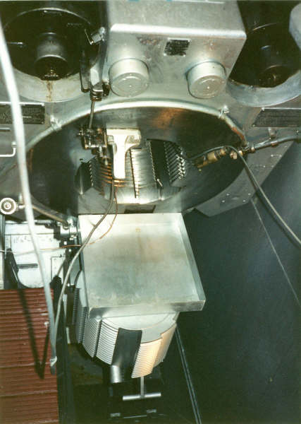
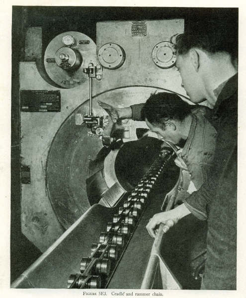
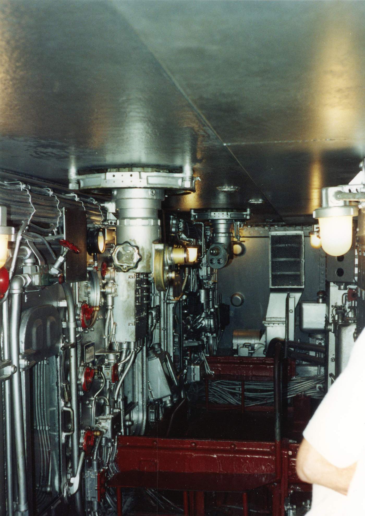 | 268k | View inside a main battery turret; In red - the rammer chain casings. | USN photo from publication "Ammunition Handling"- NavPers 16194- U.S.Government Printing Office, courtesy of Pieter Bakels. | |
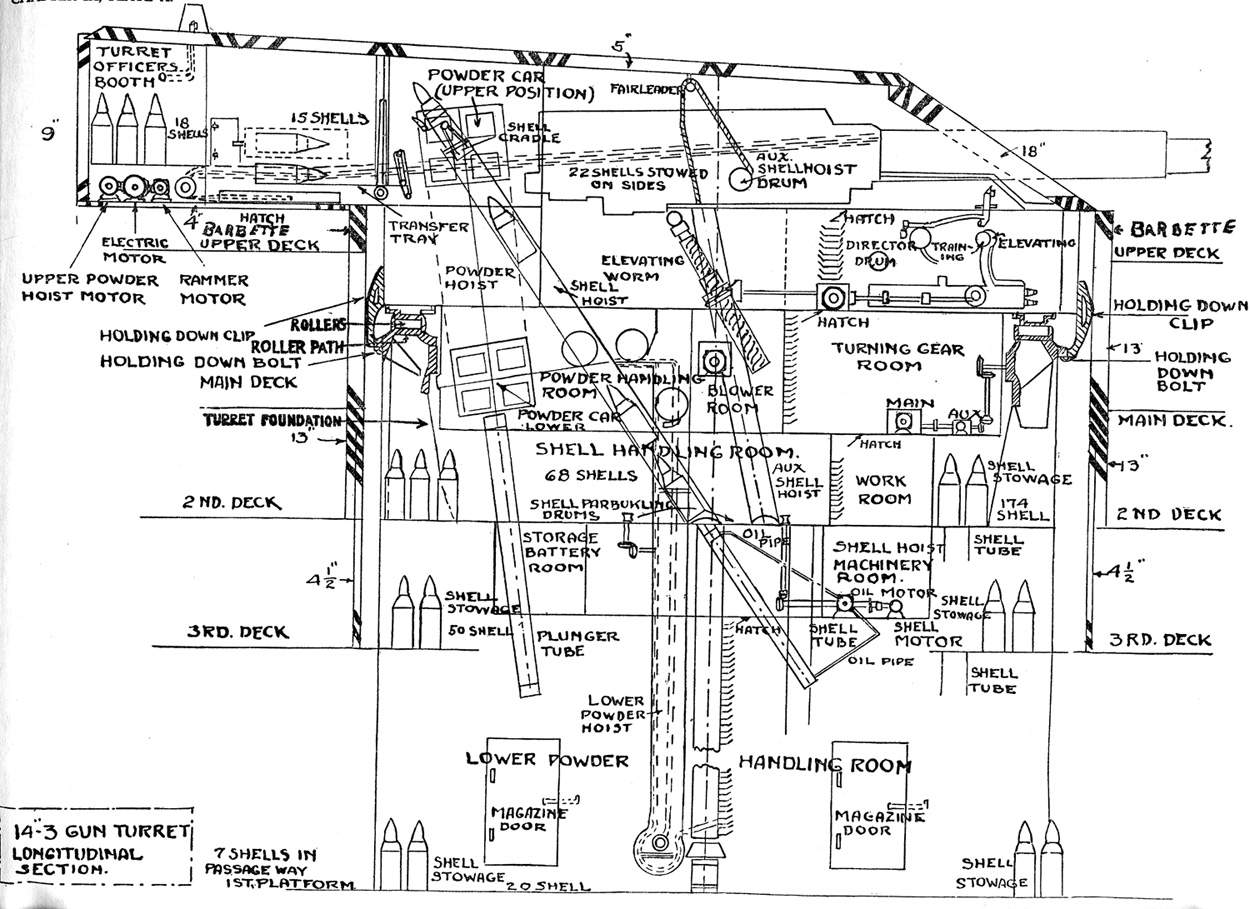 | 188k | 14-Inch 3-Gun Turret, Longitudinal Section. | USN photo and text courtesy of Pieter Bakels. | |
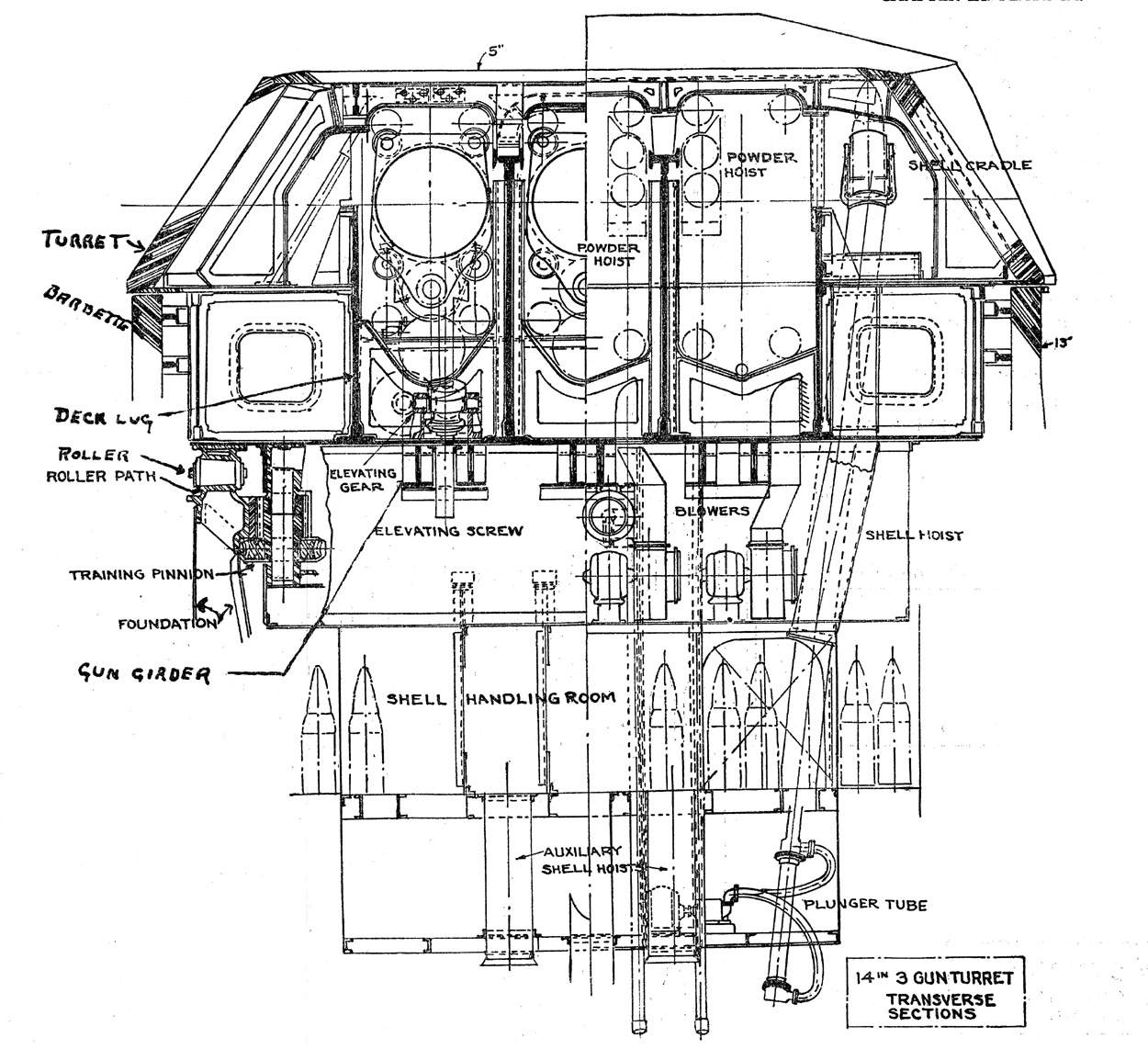 | 223k | 14-Inch Three-Gun Turret, Transverse Section. | USN photo and text courtesy of Pieter Bakels. | |
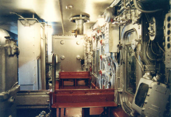
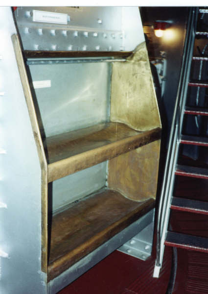
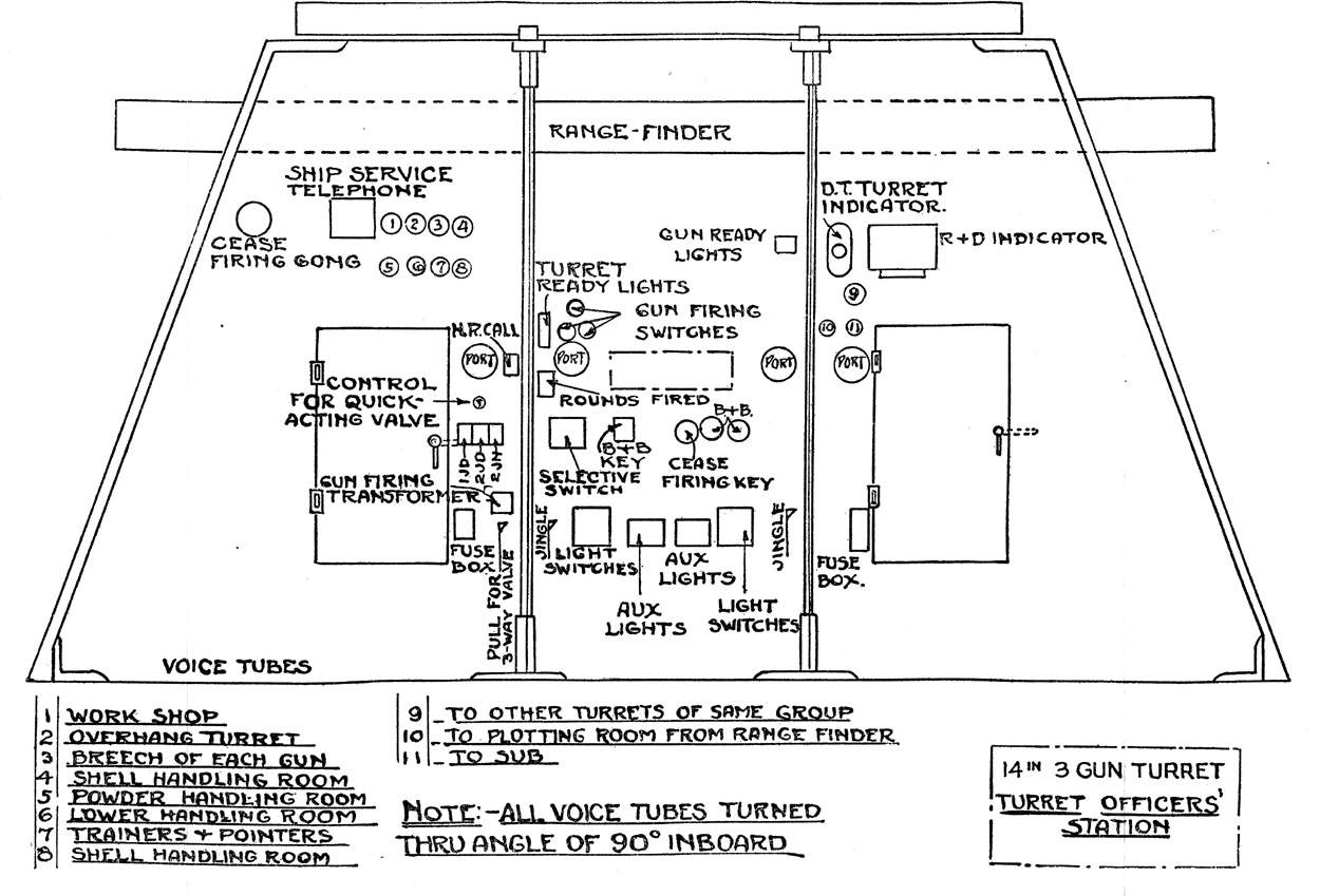 | 136k | 14-Inch 3-Gun Turret, Turret Officer's Station. | USN photo and text courtesy of Pieter Bakels. | |
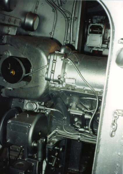
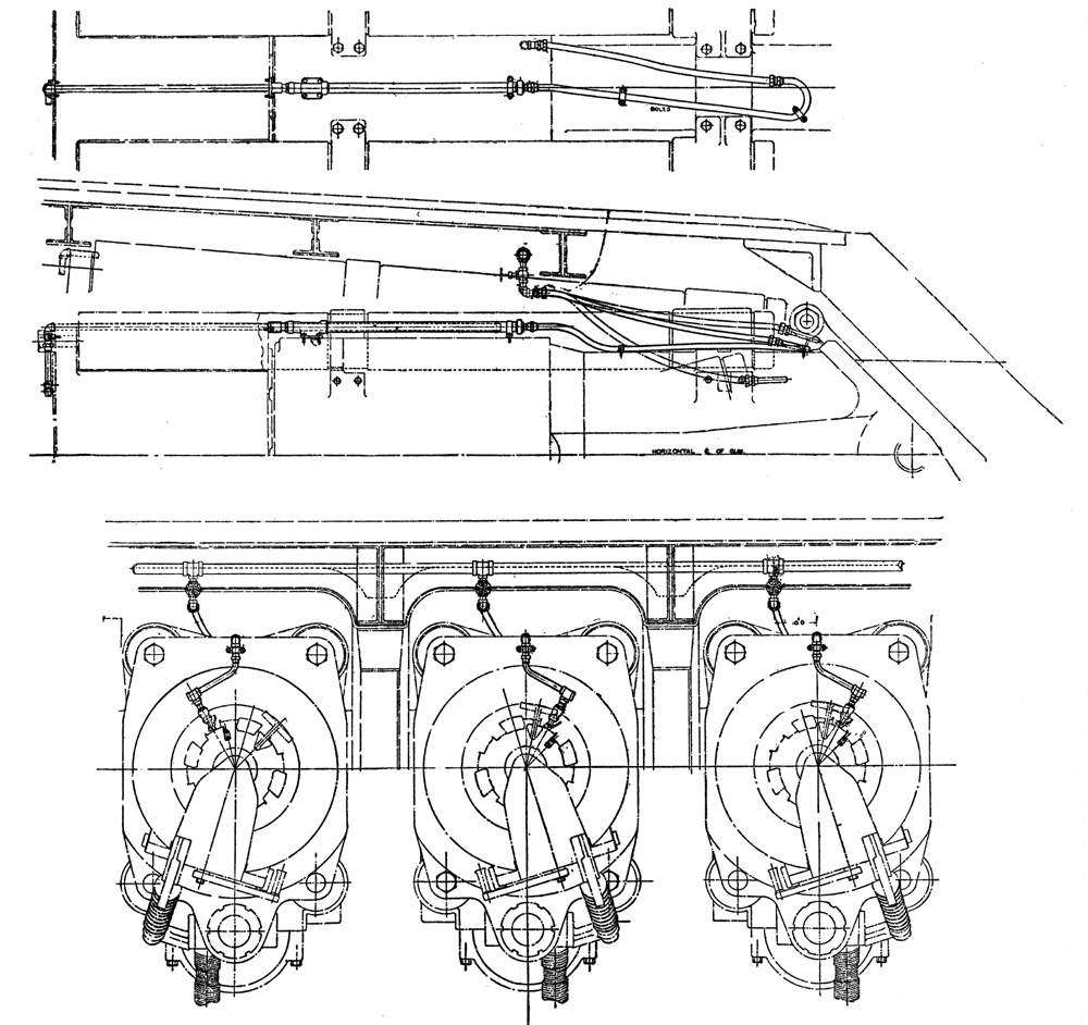 | 133k | Gas ejector system for 14-Inch turret guns. | USN photo and text courtesy of Pieter Bakels. | |
 | 22m | PDF of 16inch target projectile. | Courtesy of Pieter Bakels. | |
 | 3m | PDF of 16inch powder tank carrier. | Courtesy of Pieter Bakels. | |
 | 1.23m | "16 Gun Turret General Arrangement Plan View # 78541-143 for Massachusetts (BB-59), dated 6 October 1941. | USN photo courtesy of Pieter Bakels. | |
 |
5.8m | "Sketch of Nantucket Harbor in 1840". PDF of 13 Various G.A. (General Arrangement) prints of 16" battleship construction from 1937 - 1944. |
USN photo submitted by Pieter Bakels. | |
 | 1.23m | PDF of Faired Lines and Molded Offsets for the Indiana (BB-58), 30 January 1940. | USN photo courtesy of Pieter Bakels. | |
 |
3.5m | PDF of the Main deck compartment access & deck support of Massachusetts (BB-59), 13 November 1942. BU Ships # 461571. | USN photo submitted by Pieter Bakels. | |
| Back To US Battleship Construction Index | Back To The Main Photo Index | Back To The Battleship Photo Index Page |
This page is created by Pieter Bakels and Michael Mohl & maintained by Michael Mohl
All Pages © 1996 - 2025, by Paul R. Yarnall NavSource Naval History. All Rights Reserved.