| Click On Image For Full Size Image |
Size | Image Description | Contributed By And/Or Copyright |
|
|---|---|---|---|---|
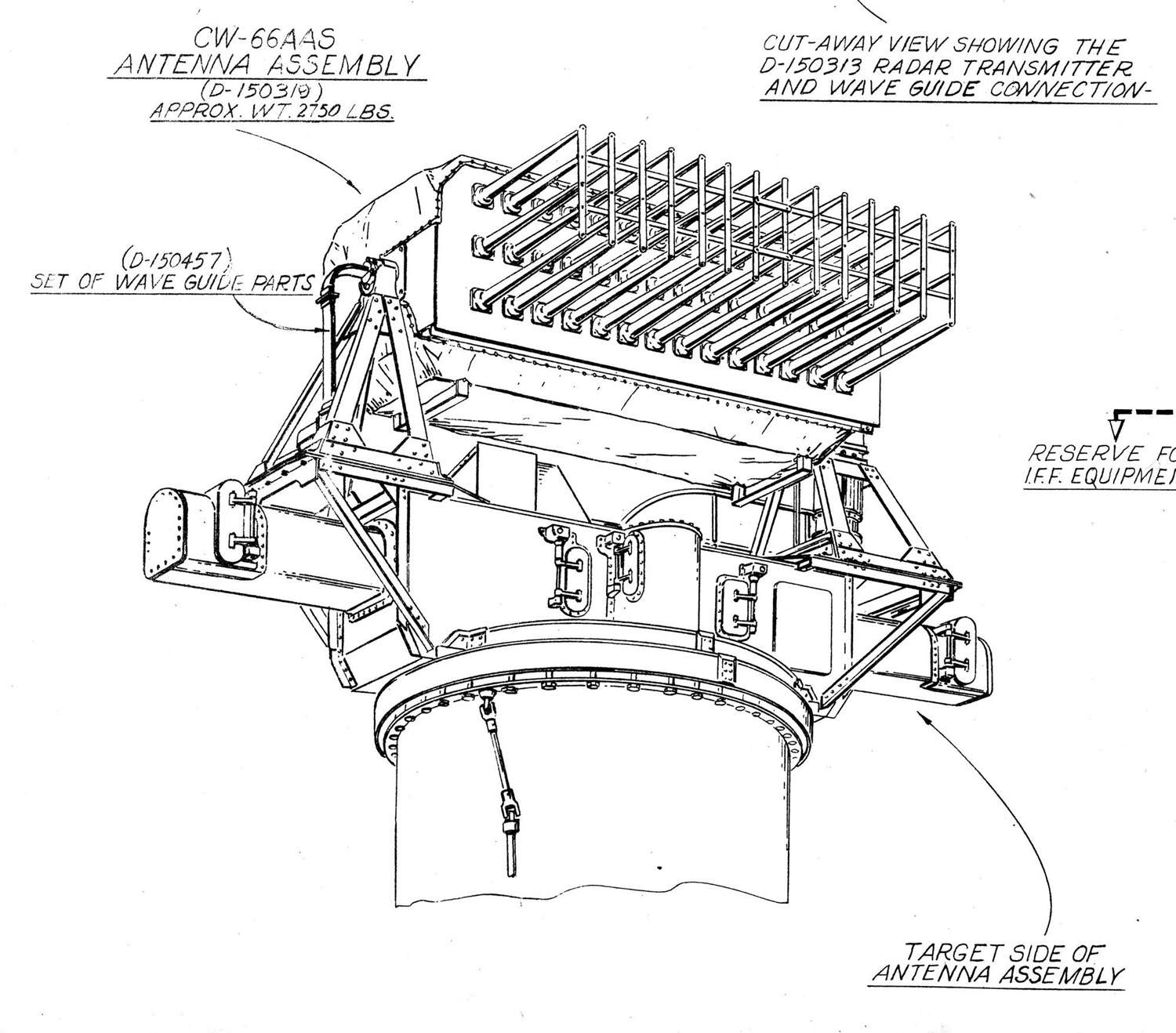
 | 2.5m | Radar Equipment Mk.8 The Antenna of Mk.8 Mod.1 was a 14-element MUSA (multi-unit-steerable-antenna) array in which the elements were horizontally aligned in broadside. That provided the necessary horizontal directive and permitted the radiation lobe to be steered without antenna motion, changing the phase difference between adjacent radiators. It was supported on top the directors Mk.34 and Mk.38 by an arrangement that moved it up or down to compensate for ship motion. It could be leveled between +15- and -15 degrees. 42 tapered, solid polystyrene rods (polyrods) projected from it in 14 vertical groups of 3. Each rod was about 3 ft. long and fitted into the end of a waveguide that supplied voltage for it. A group of 3 rods was called a trident and functioned as a separate element of the antenna. Scanning was accomplished by means of 13 mechanical phase shifters that continually shifted the phase of the voltages supplied to the tridents. They rotated in ball bearings, driven by a motor, mounted at one end of the antenna. Near this drive motor, a gear-shift motor was mounted for 2-speed scanning. Auxiliary equipment allowed the operator to start, stop or reverse the scan or select scanning speeds. A synchro generator was mounted on the assembly for indications at a remote point of the position of the antenna lobe during low-speed scan. During high-speed scan, a solenoid clutch disengaged the synchro generator. This radar equipment was used primarily for Main Battery fire control. Range accuracy was excellent. Bearing accuracy was practically as good as optics. Spotting in range was excellent. Fall of shot within 1000 yards of target range was accurate to the nearest 100 yards. Spotting in bearing was not practical for small deflection errors. The antenna was stabilized in level from the stable vertical in Main Battery Plot or local rangefinder. Level input to the antenna was necessary since the narrow beam would roll above and below the target if the antenna was not held on level. Range was transmitted to Main Battery Plot electrically. All operating and control units were at first mounted in the director, later some of it was mounted in Main Battery Plot. Operation required 1 radar operator and the director train operator. The range at which surface targets could be reliably detected exceeded the range of the battleship's 16-inch /45 cal. guns and range-keepers. Range and bearing discrimination was good. Important tactical information regarding the composition of targets could well in advance to action be obtained. Three sweepes were provided: Main, Expanded & Precision sweeps. Main sweep made it possible to see to about 90,000 yards. Range measurement to only 45,000 yards. This sweep was used for initial contacts and for obtaining tactical information concerning number, disposition and movement of targets. Expanded sweep made it possible to expand the first 20,000 yards of range for better range discrimination. Precision sweep selected a given range indicated on the range unit and showed any target within 1000 yards of this range in proper range relation. It was used out to 45,000 yards. Range spotting was obtained by using precision sweep and high-speed bearing sweep. | USN photo and text courtesy of Pieter Bakels. | |
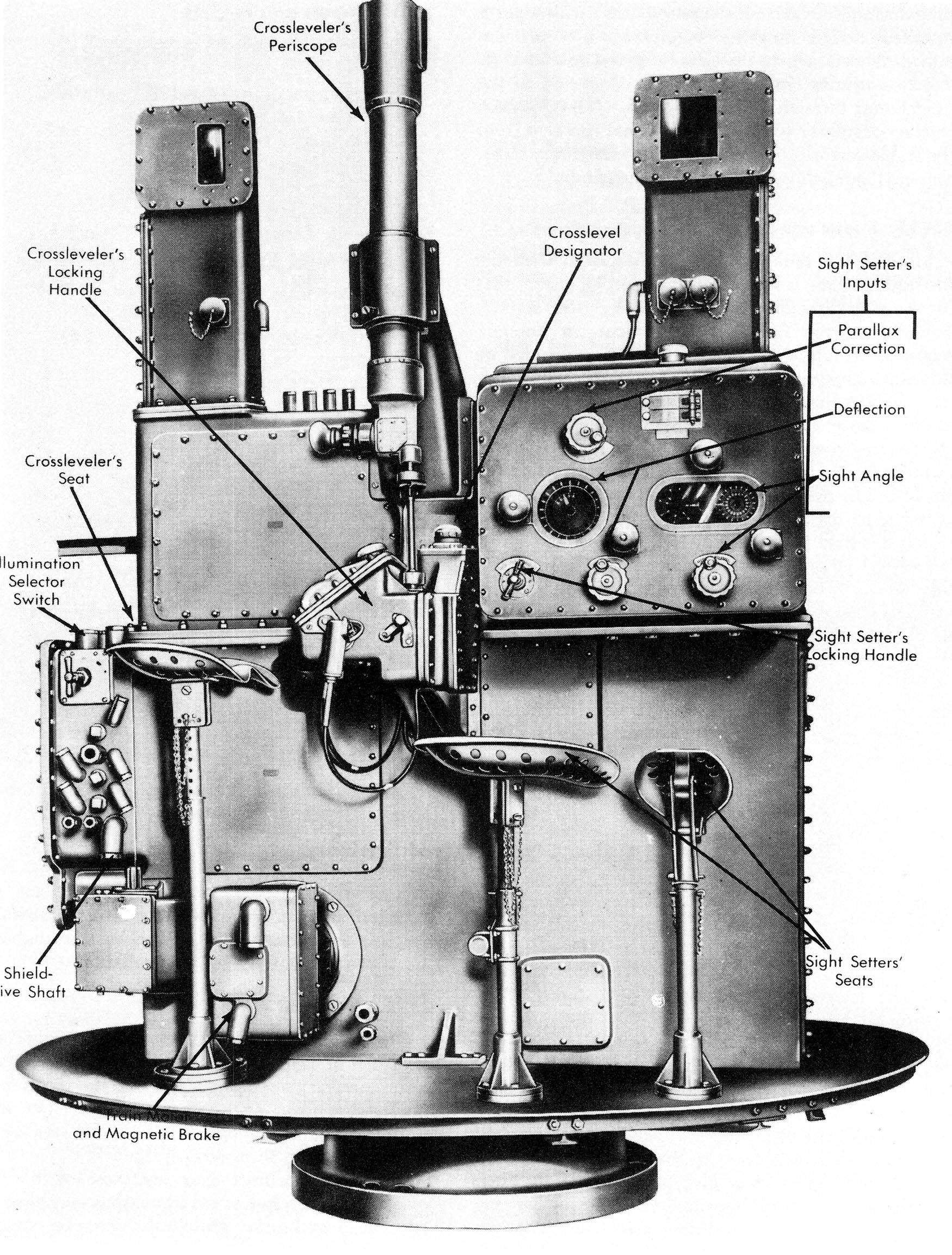
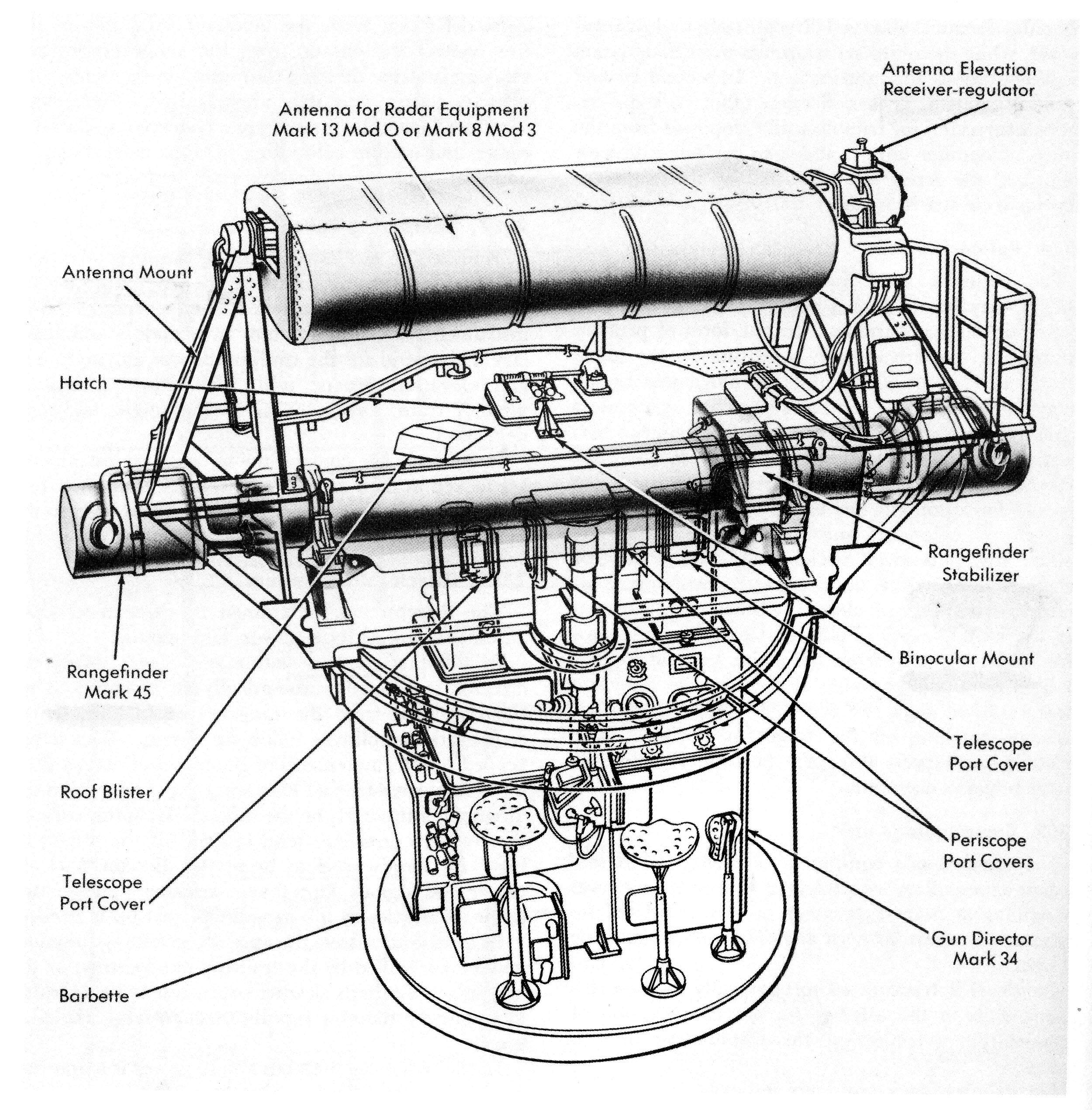
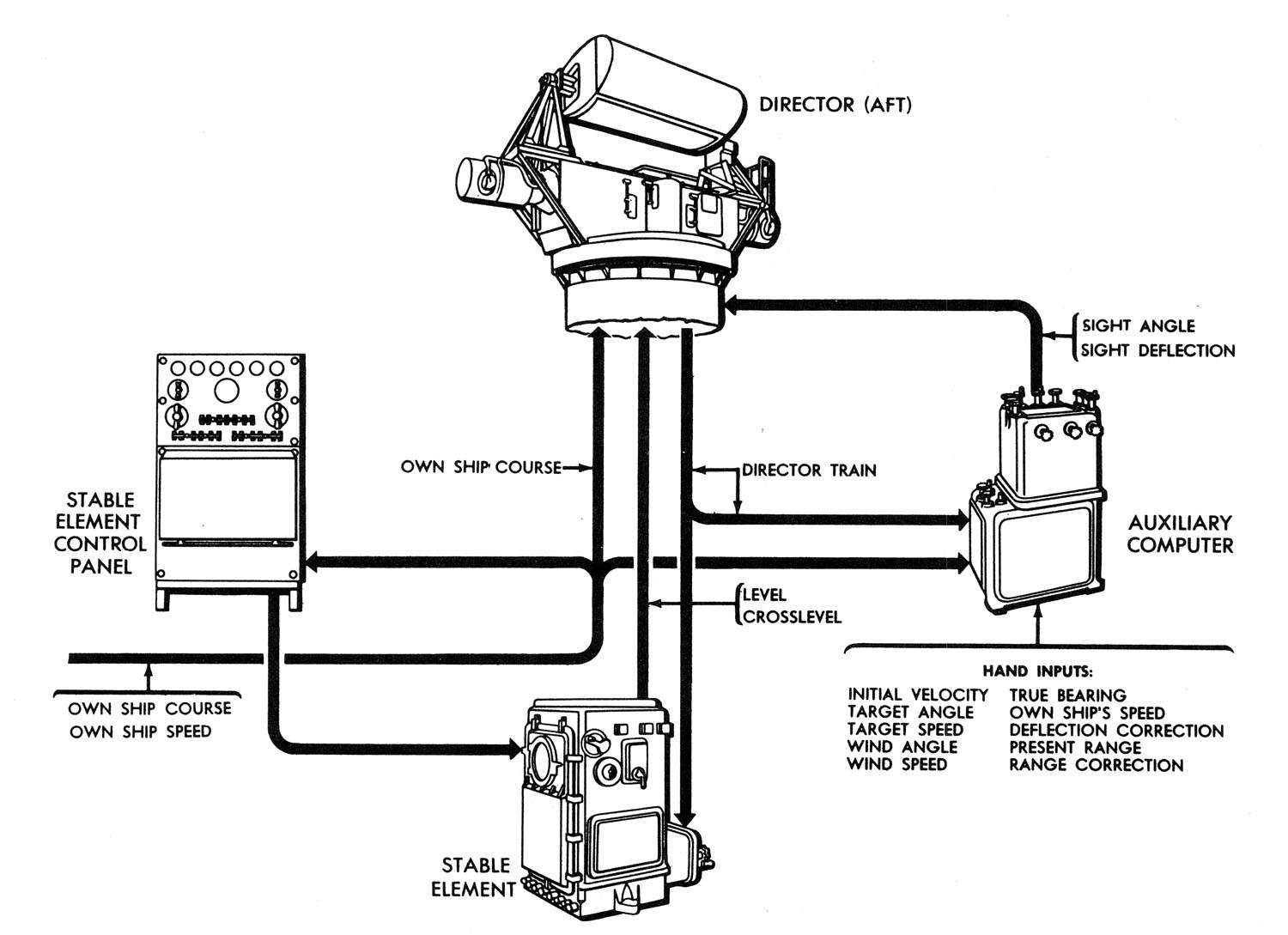
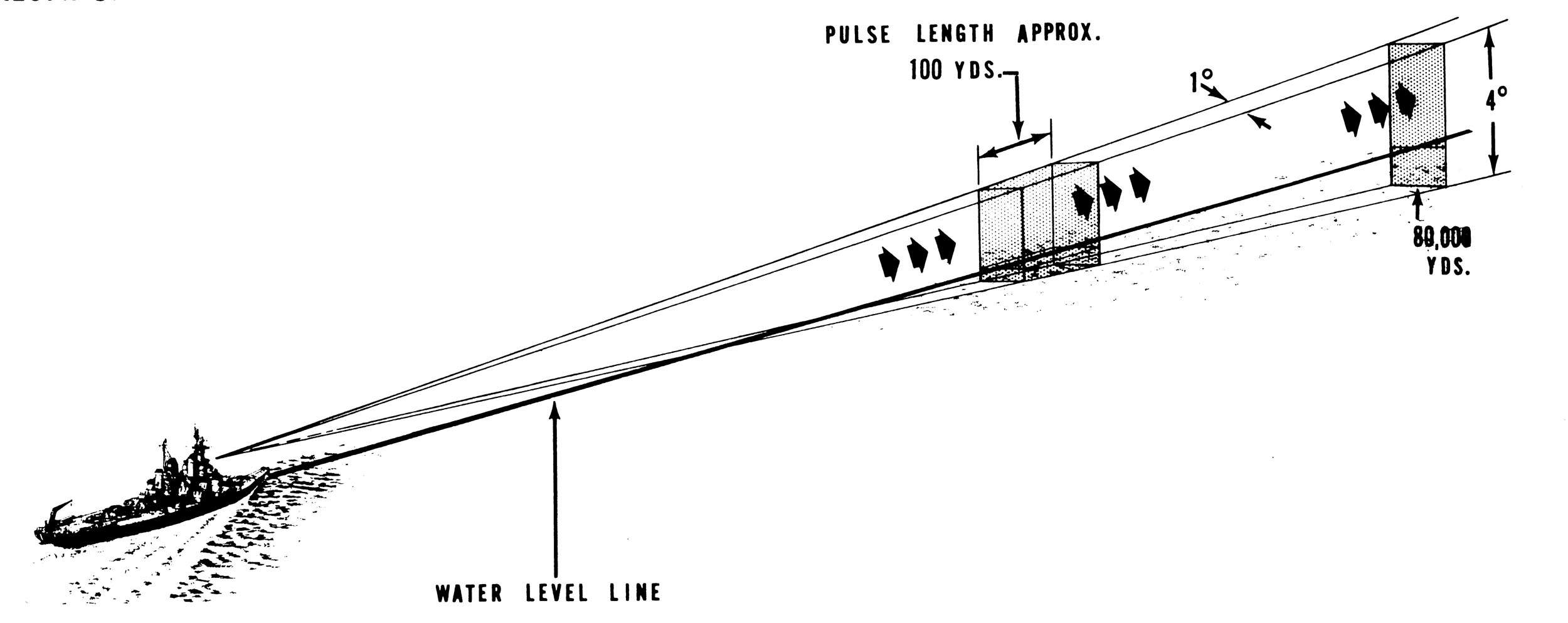
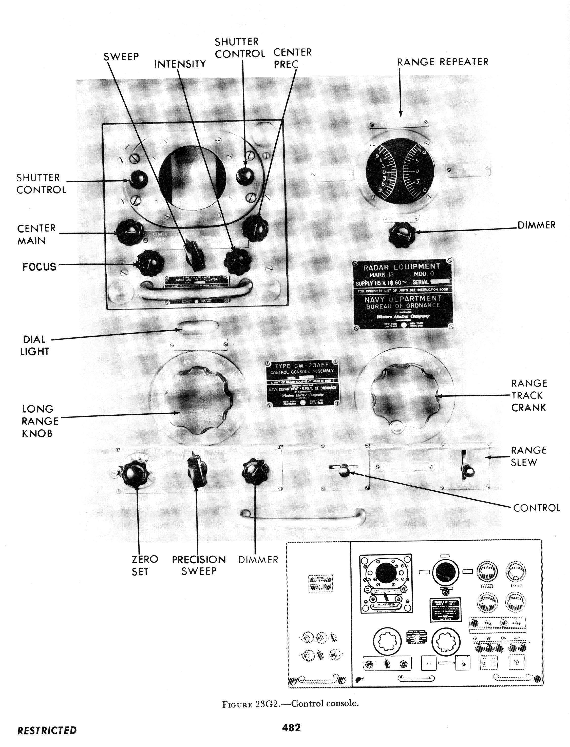
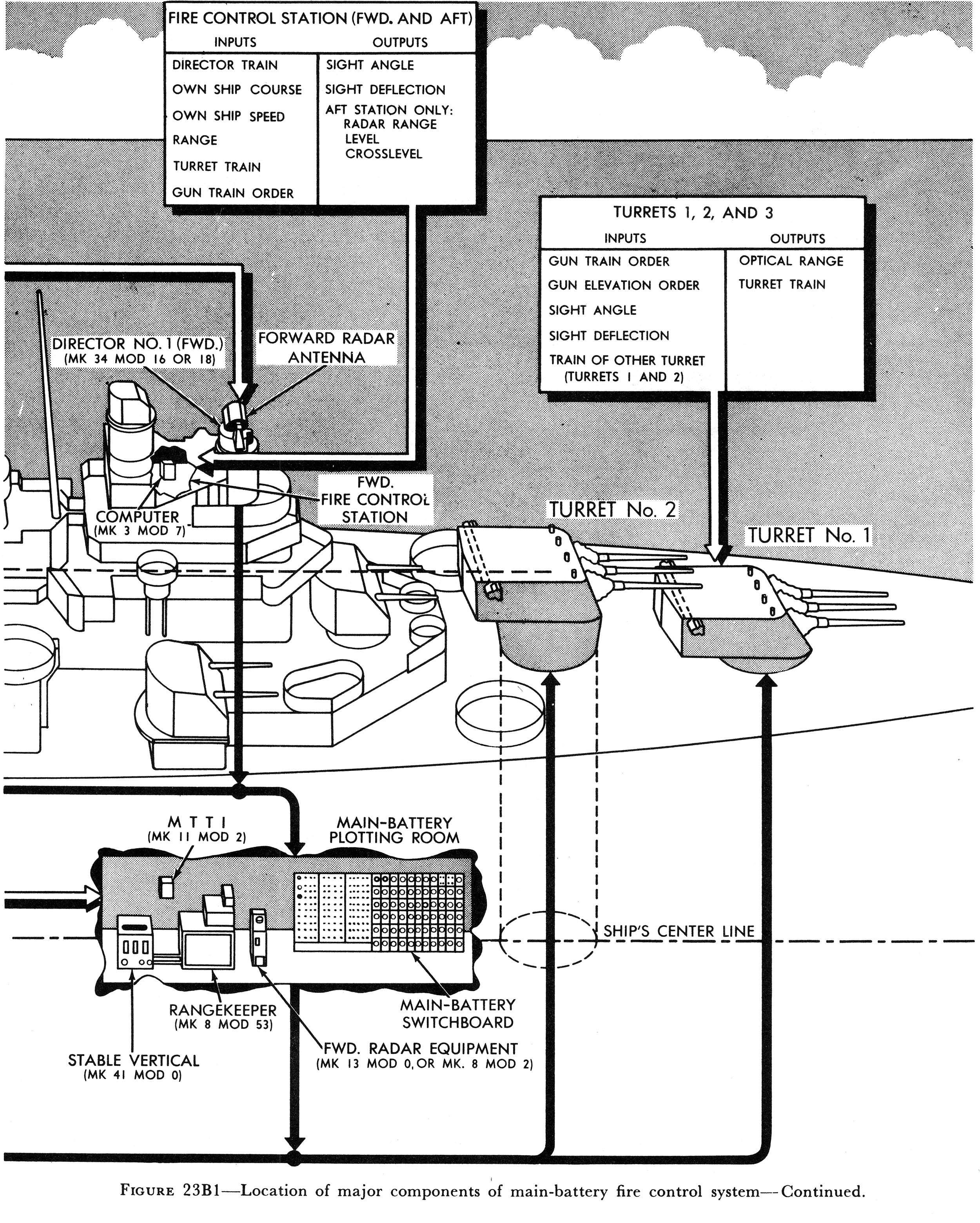
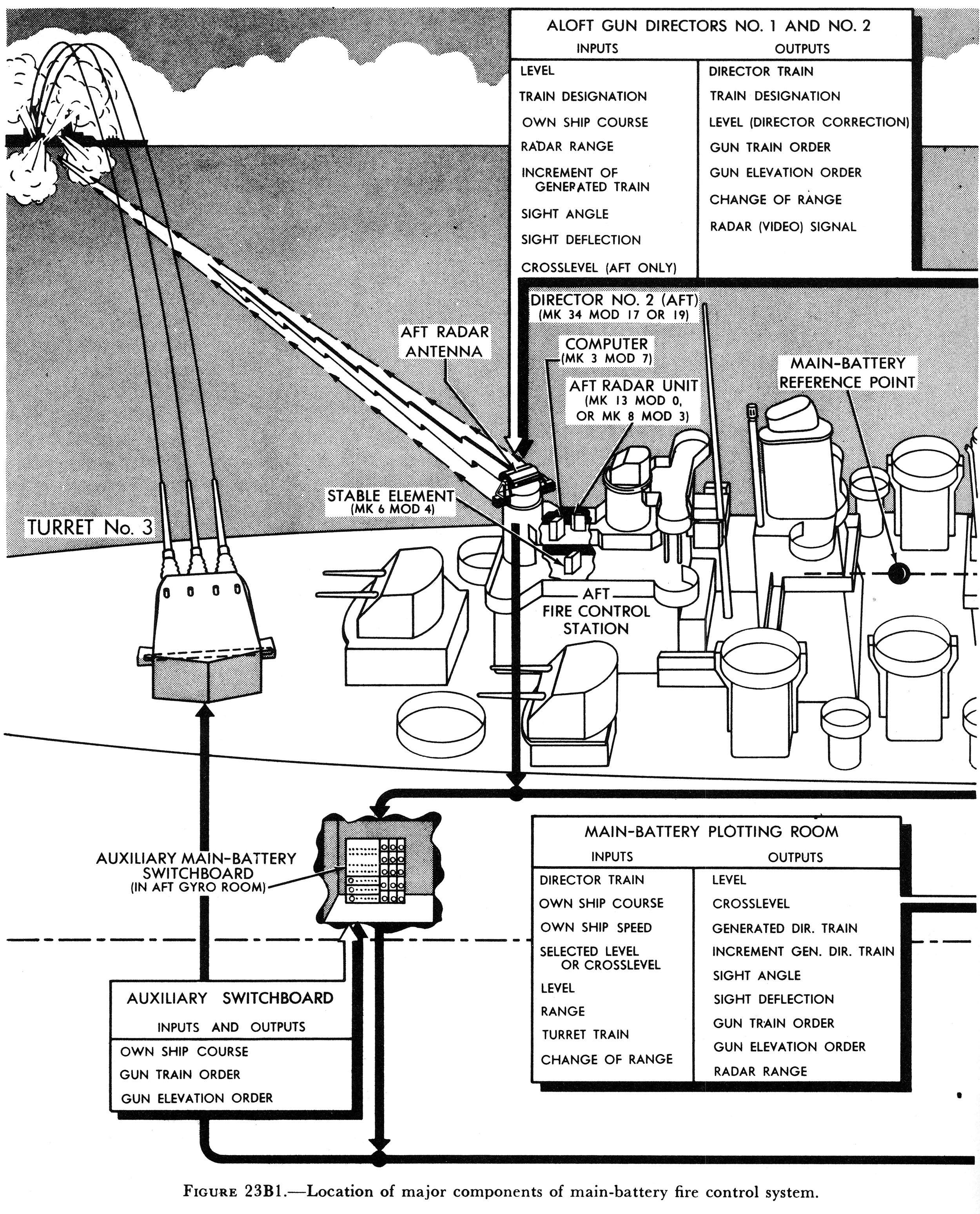
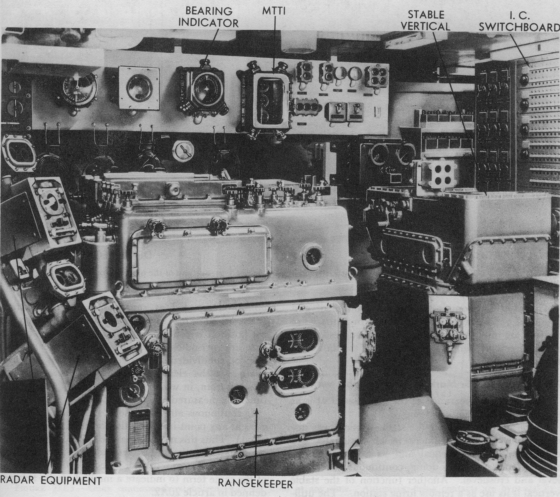
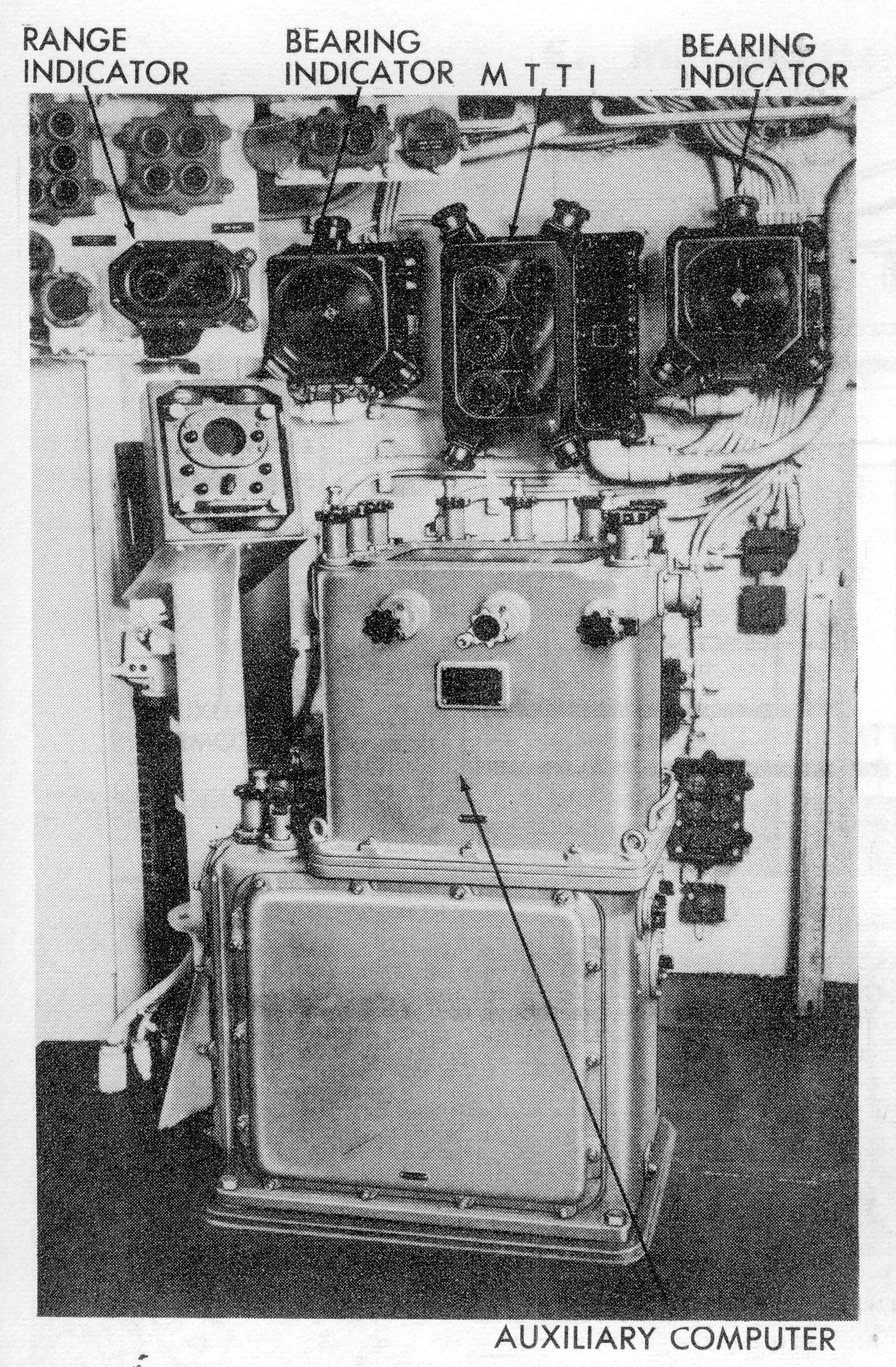
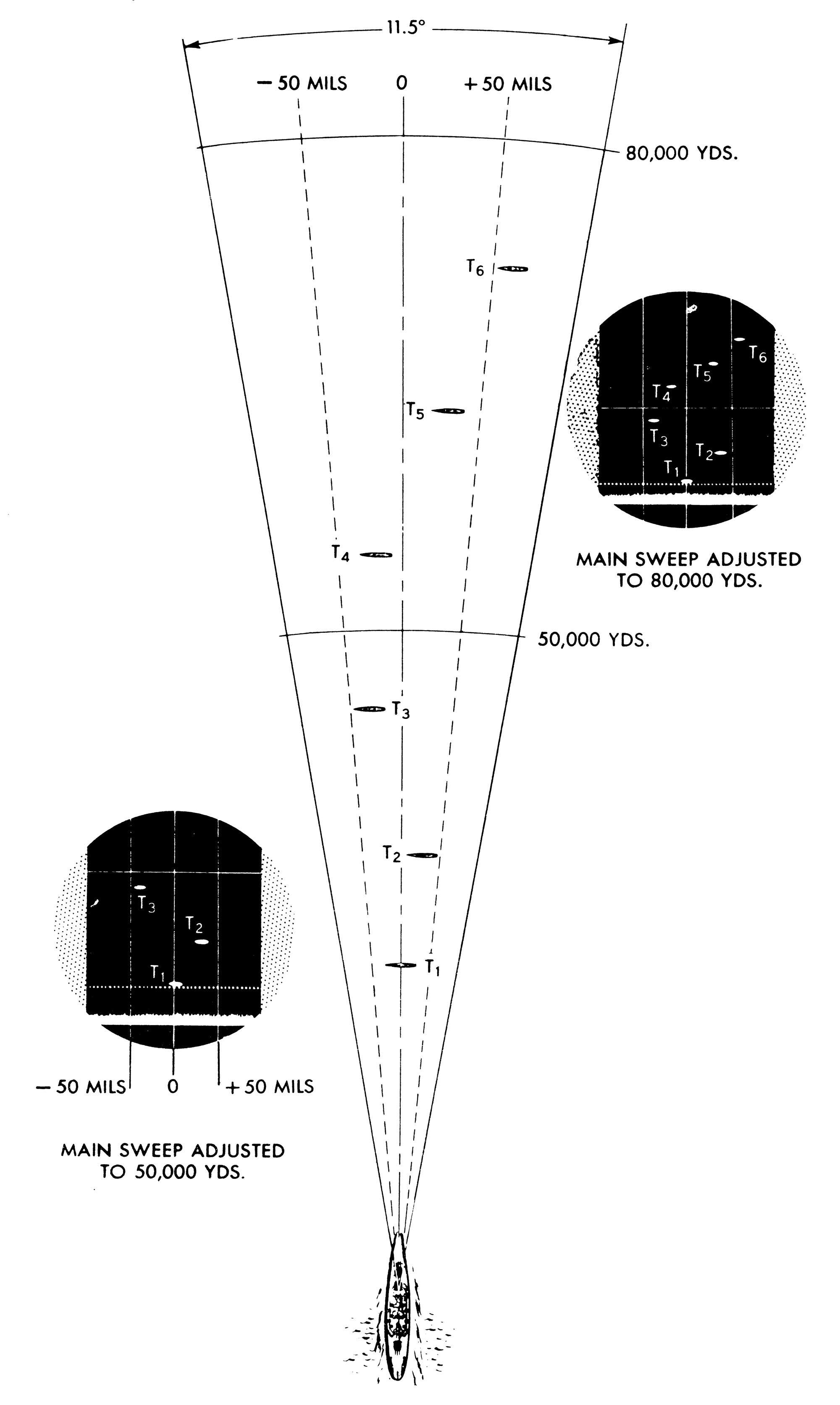
 | 1.0m | By late 1945 the Mark 8 Main Battery FIRE CONTROL Radar, mounted on top of a Main Battery Fire Control Director Mk.38 or Mk.34 was replaced by the 3cm Mk.13 or converted to the very similar Mk. 8 Mod. 3. The Mk. 13 was the last director radar to be produced by Western Electric for the US Navy. The complex mechanically scanned, polyrod array of Mk.8 was replaced by an 8ft x 2ft parabola within a radome with a gain of 14,000 and a 0.9 degrees wide and 3.6 degrees high beam, scanned by rocking it about its vertical axis (‘rocking horse’ motion). This caused the narrow beam to progress back and forth through a horizontal arc of 11.5 degrees (200 mils) five times in each direction per second. The center of the scanning arc was rigidly aligned with the director line of sight, so that when the director was trained on a target, accurate bearing indication was given by the radar. With respect to the bearing of the director, the radar beam scanned an area between +5.75 and -5.75 degrees. Range and accuracy performance were comparable to that of Mk.8. Mk.13 used 50kW pulses (0.3 microseconds, PRF 1800). The scope presentations seen on the control console and the remote range and train indicators were identical and were B-type presentations. In this type of presentation, own ship was at the bottom of the scope and the picture seen was that of a narrow, wedge-shaped segment of the earth. Whenever the radar equipment viewed a target, a bright spot (the echo from the target) appeared on the scope. The centerline or zero bearing line was aligned with the line of sight of the director. The distance between vertical lines represented intervals of approximately 50 mils in bearing. When the field of view started at zero yards, the wide horizontal line at the bottom of the scope marked the outgoing pulse. All ranges were measured upward from this horizontal line. The narrow dotted and solid horizontal lines were called the normal-range line and the long-range line respectively. They were independent of each other. The forward main battery & aft main battery control units or control consoles (in CA’s/CL’s in the early 1950's) were located in the Main Battery Plotting Room near the Mk.8 range keeper and in the after main battery control station topside, adjacent to the Mk.3 auxiliary computer. There was provision for shifting control to a remote-control unit at the control officer’s station in an associated director. Two remote range and train indicators were located in each director for the trainer for getting on target and to provide the control officer with continuous target data and to enable him to spot the fall of shot. In addition two remote range and train indicators, one for each radar, were installed adjacent to each main-battery range-keeping instrument- the Mk8 range-keeper in the plotting room, the Mk3 computer in the forward topside control station and the Mk3 computer in the after topside control station. These remote indicators gave the same B-scope presentations seen on the control consoles and associated range counters gave direct range readings for use of the range-keeper or computer operator. Fall of shot could also be spotted from remote indicators. Other components of the radars were below decks. Three types of sweep were available in the Mk13 radar: 1- Main Sweep On main sweep the operator could view out to 80,000 yards. The total range appearing on the scope at any time could be varied from 40,000 yards to the entire 80,000 yards. It was recommended that the field of view be set to 50,000 yards. The operator could then view any 50,000 yard section of these 80,000 yards by adjusting the center main control on the console, which moved the field across the scope in the same manner that a window shade may be moved behind an opening. There were three solid bearing lines, the outer lines each 50 mils out from the center bearing line. The total width of the scope was approximately 200 mils, 100 mils either side of the center bearing line. Two range lines were visible on the main sweep. The long-range line, which was solid, was controlled by the long-range knob and moved over the face of the scope to the maximum of 80,000 yards. The normal-range line, which was dotted, was controlled by the range-track crank and moved over the face of the scope only to 50,000 yards. The operator shifted the range line until it touched the bottom of the echo. The range to the target could then be read from the long-range dial or the range repeater. 2- Precision Sweep-Normal: On precision sweep the operator could view to a maximum of 50,000 yards, but only 2,000 to 4,000 yards of this at a time. The desired visible field on precision sweep, which could be any value between 2,000 and 4,000 yards, was set by an internal adjustment and usually was not changed by the operator. The operator could select any 2,000 to 4,000 yard section out of the normal 50,000 yards available. This was done by operating the range-track crank which moved the visible field in the scope in the manner of a roller shade. The range line was dotted and fixed in the center of the scope. On precision sweep, the field and not the range line moved during ranging. When the echo came to rest upon the range line, range to the target could be read from the range repeaters. Bearing lines were made up of dots indicating spaces 200 yards apart. 3- Precision Sweep- Long Range: The long-range unit could be used with precision sweep out to 80,000 yards but range had to be read from the long-range dial with its coarse graduations and could not be as accurate as with the normal-range unit, the reading dials of which had graduations as small as 10 yards. Precision sweep-long range was used for observation only; range was not transmitted to the range-keeper. Interference: Several types of interference could be encountered in the operation of the Mark 13 radar: Double echoes When ranging on strong echoes from nearby targets, echoes could appear on the screen. This was due to the reflected energy from the target ship hitting the radar ship and being reflected a second time from the target ship. An operator had to become familiar with this phenomenon by observing such targets on a practice run. Shore interference When observing shore lines, there would be a small area (generally of negligible importance with the excellent discrimination of the Mark 13 radar) in which targets could be obscured by land background. Air targets While the equipment was not designed for tracking aircraft and did not provide for pointing indication or measurement of elevations, the 4 degrees vertical beam would pick up echoes from aircraft. Air targets could usually be distinguished from surface targets by their high speed and rapid fluctuations. Echoes from aircraft flying over land were often hidden in the land echoes. If the antenna was elevated so that the lower edge of the radar beam was barely above the land, a means was provided for the detection of enemy aircraft approaching low over the land. An aircraft flying 2 degrees (half-beam height) above the land would produce an echo on the screen. Ranges and bearings (but not elevation angles) could thus be obtained. Because of this good discrimination in elevation, warning of approaching aircraft could be obtained when it might not be possible with other equipments. An 11.5 degrees sector could be covered by each Radar Equipment Mark 13 without movement of the gun directors. Interference from other radars operating in the vicinity could produce a background noise on the scope which would not, in general, affect operation. At times, particular in stormy weather, large, irregular and fluctuating pips could appear on the screen. This was called sea return and was caused by echoes from waves. Reducing the receiver gain would eliminate much of the sea return and tended to sharpen the outline of the target echoes. Spotting: The Mark 13 radar could be effectively used to spot fall of shot in both range and deflection. Shell splashes appeared on the B-scope as fluctuating echoes which lasted for several seconds, depending upon the size of the projectile and the range. Salvos produced larger or multiple echoes on the scope. Radar spotting proved to be both accurate and reliable to the full range of the guns and was of course, independent of visibility conditions. In using the B-scope for spotting, precision sweep gave the best indications of shell splashes and was normally used. For best results, accurate tracking with the target echo kept adjacent to the range line and bisected by the center bearing line was essential. The error of the MPI from the target echo could then be easily estimated, using the dots on the bearing line, which were 200 yards apart, as a yardstick in range. It was also helpful in deflection spotting to keep in mind that the average width of the splash echo could be taken as approximately 18 mils. | USN photo s and text courtesy of (NavPers 16116-B) via Pieter Bakels & Don Greer. | |
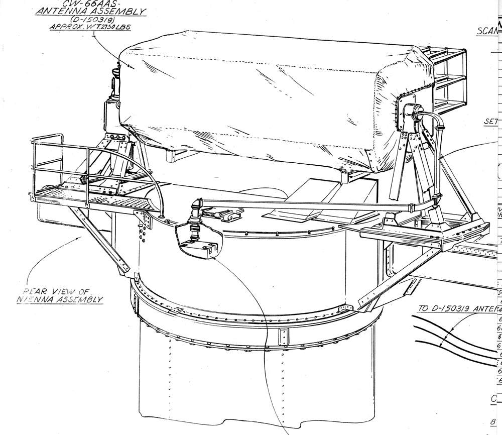
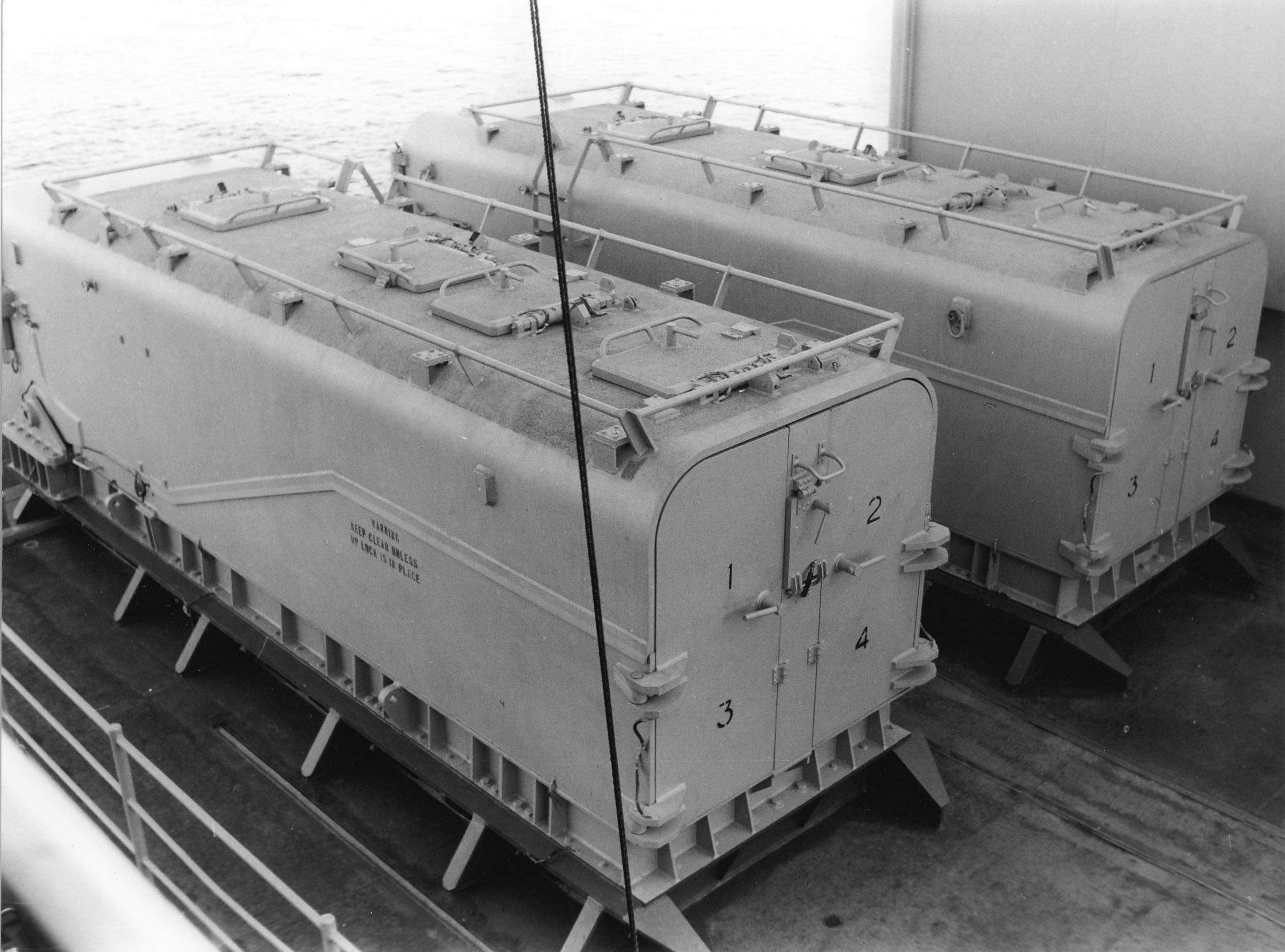
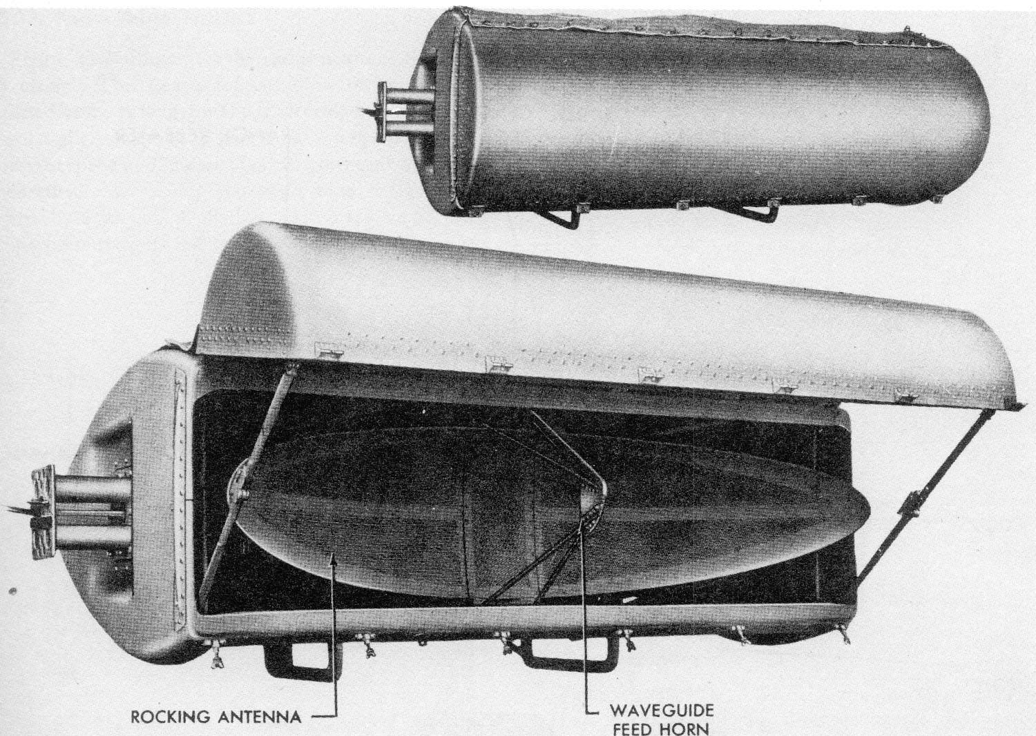 | 352k | Antenna assembly, radar equipment Mk.13 Mod 0, front open and closed. Seen here is a PDF of Mark 13 Mod 0 Unit Outline Dimensions Rotating Structure, March 1945, # 1 - 3. | USN photo s and text courtesy of (NavPers 16116-B) via Pieter Bakels. | |
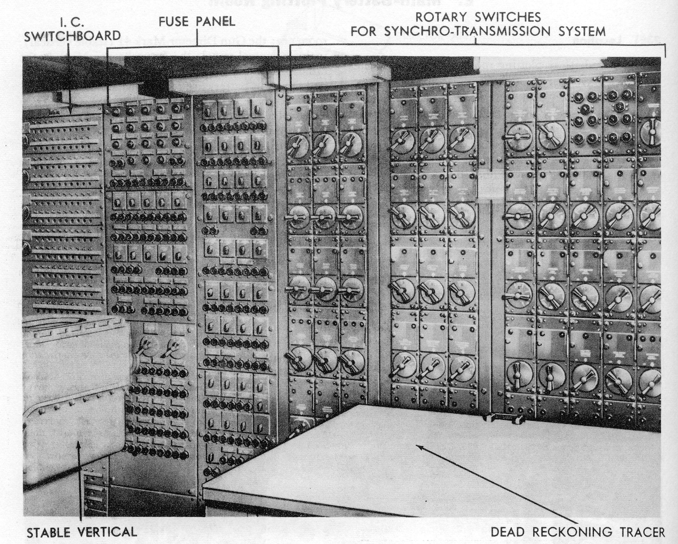 | 1.1m | The main battery switchboard located at one end of the plotting room. | USN photo and text courtesy of (NavPers 16116-B) via Pieter Bakels. | |
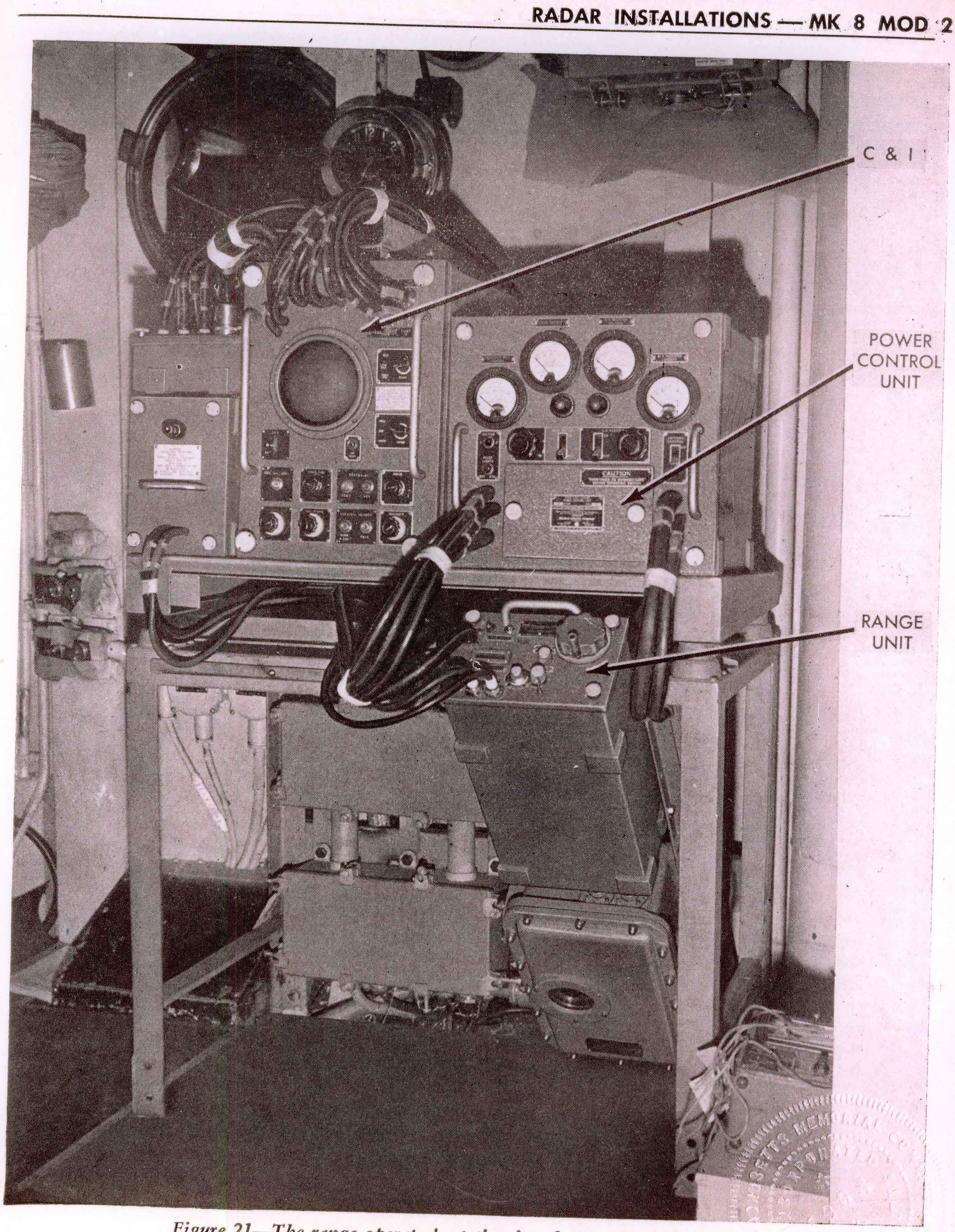
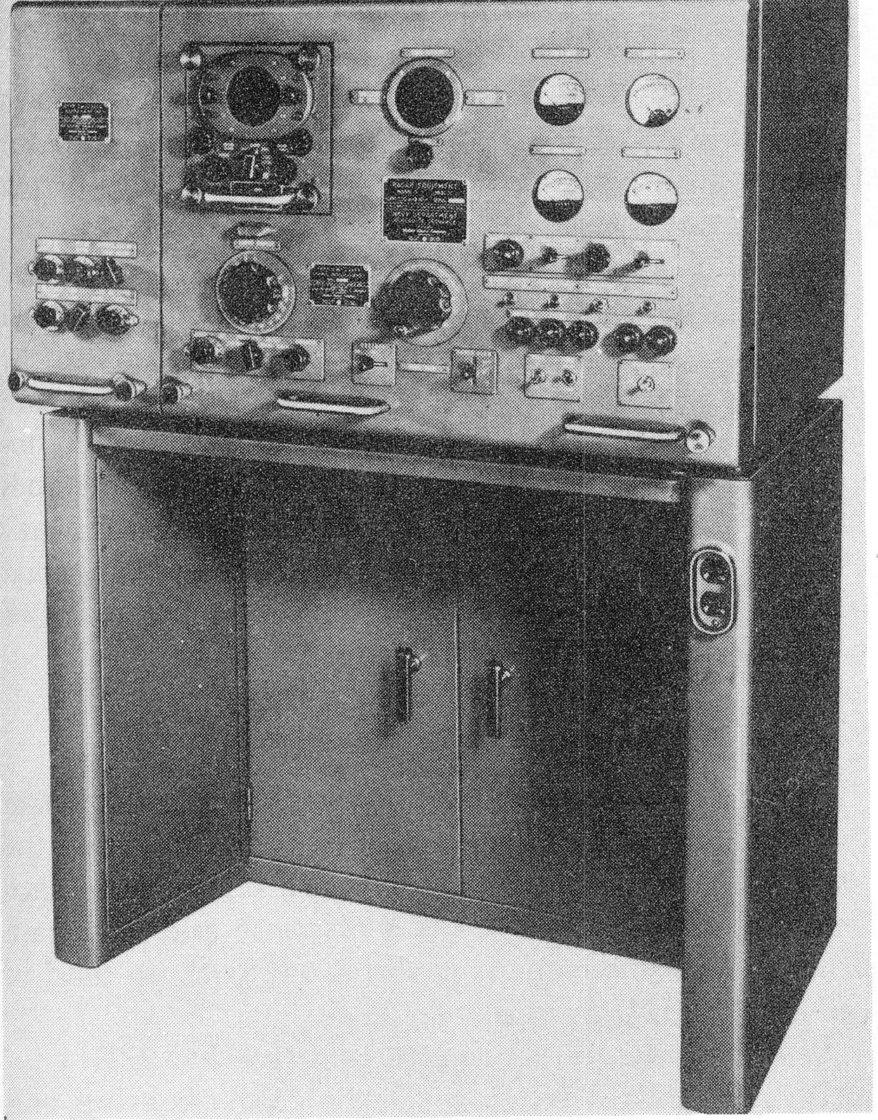 | 646k | Radar console used for radar equipment Mark 13 Mod 0. | USN photo and text courtesy of (NavPers 16116-B) via Pieter Bakels. | |
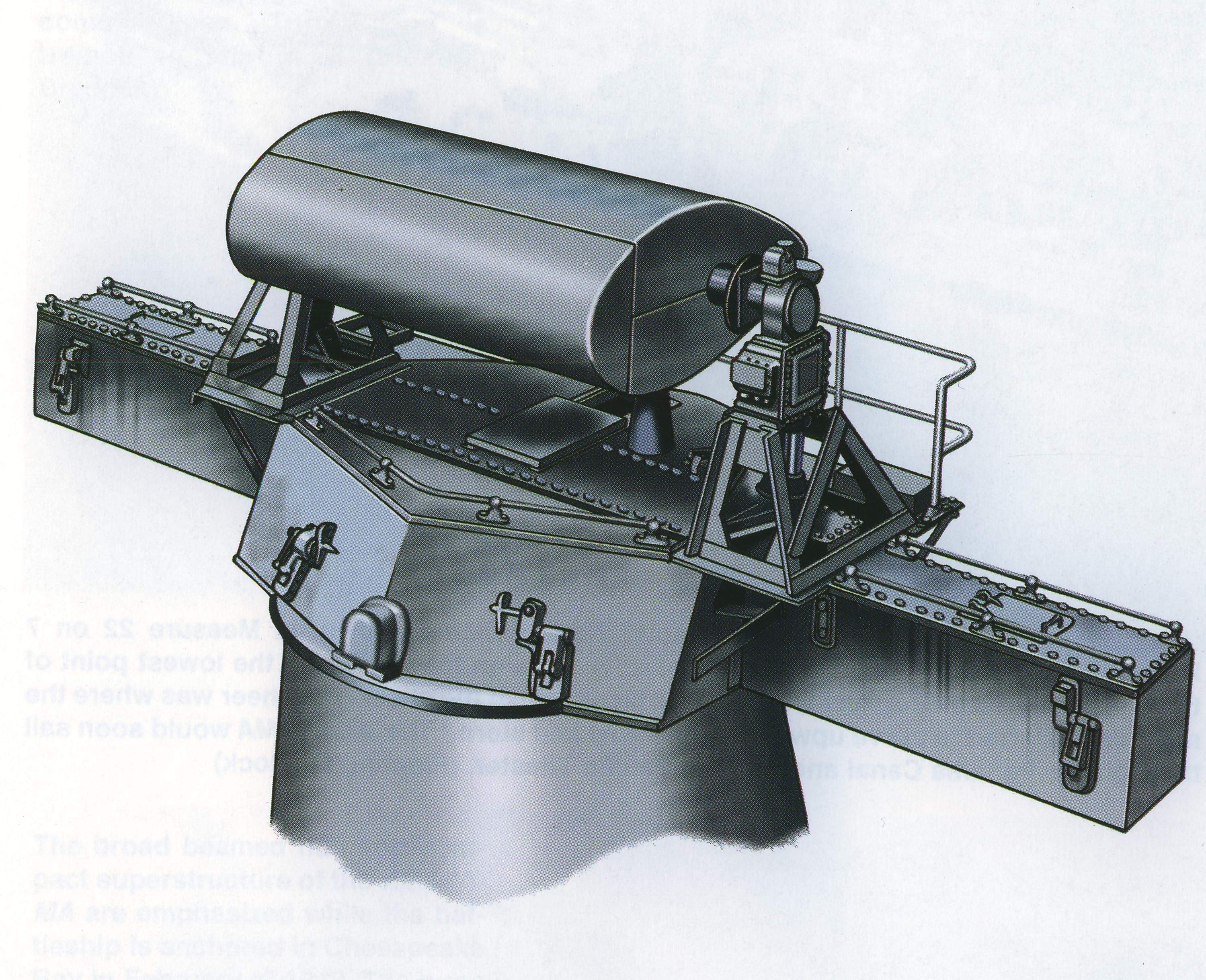
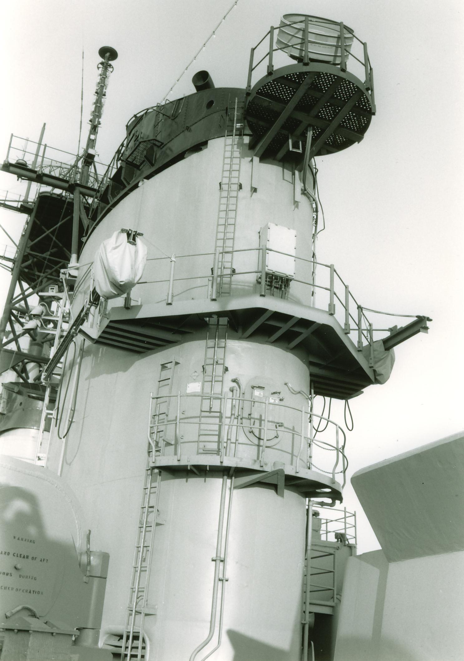
 | 870k | Gun Director Mk.34, front view without shield. Seen here is a PDF of the Iowa (BB-61) in 1985 of her after main battery director with radar Mk 13 antenna. | USN photo and text courtesy of (NavPers 16116-B, September 1950) via Pieter Bakels. | |
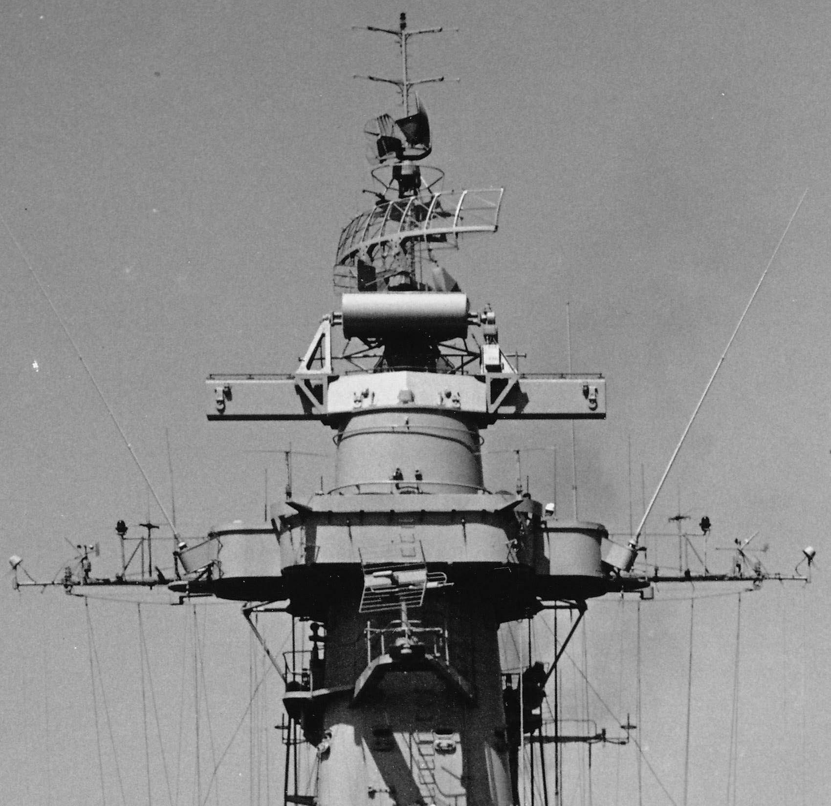 | 266k | New Jersey (BB-62) during ops off Korea showing her MK13 Main Battery Fire Control radar atop Spot One. Spot One (the Mk.38 Main Battery Director on her Foretop) has radar equipment Mk.13, above that, her SPS-6 radar antenna is visible with a Zenith Search antenna mounted in place of the SG antenna and short-range, ship-to-ship antennas, AT-150, and AS-390, ship-to-air, hardly visible. On both sides of her Forward Air Defence Platform additional whip antennas for long-range reception and transmission and two extra TBS antennas have been mounted. Below this, a TDY jammer. On her yardarms “Derby”, CAGW66132, omni-directional, warning-type antennas and some IFF antennas. “Ski- Pole” IFF antennas project P./S. on platforms from her fighting tower. | USN photo and text courtesy of Pieter Bakels. | |
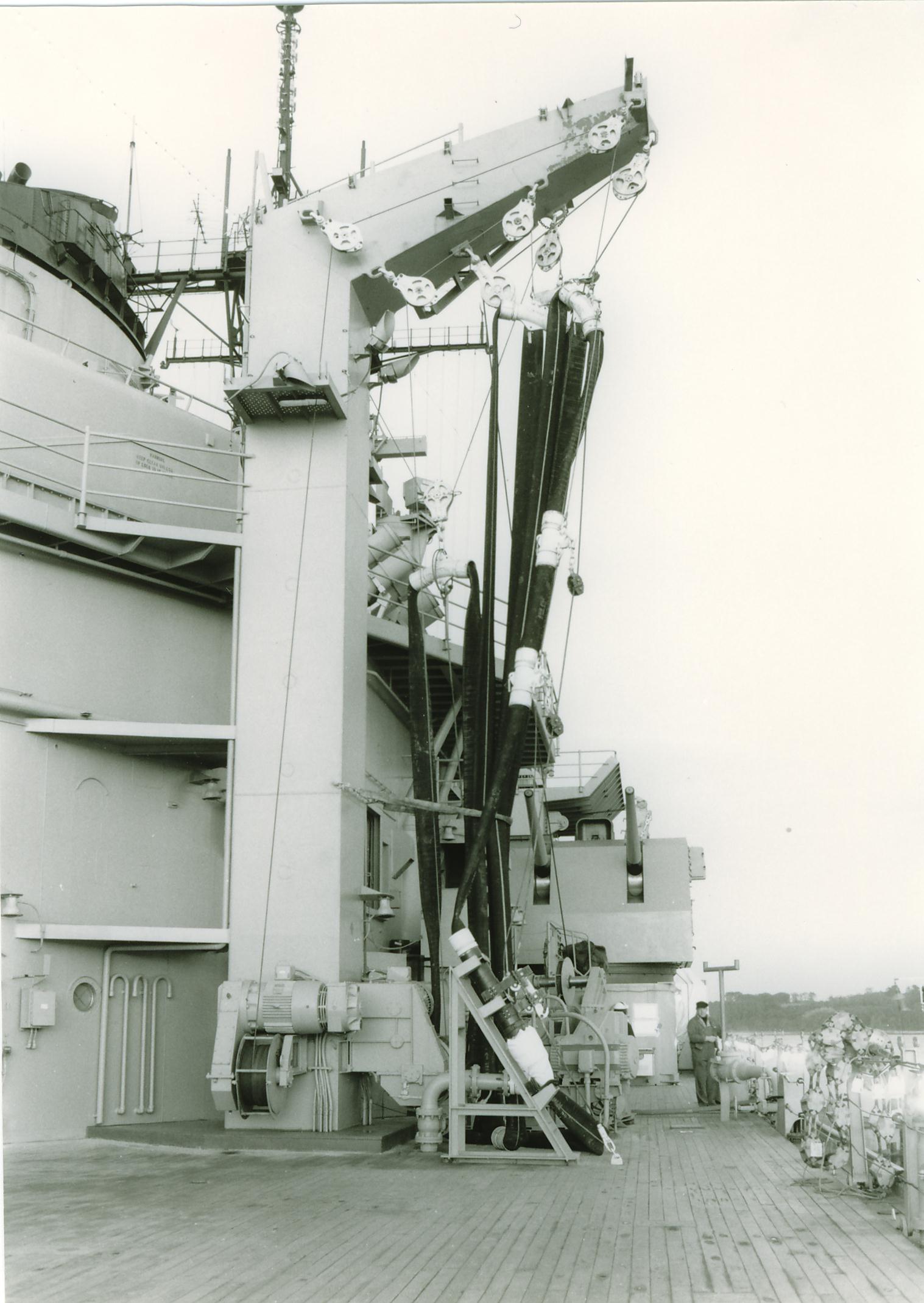
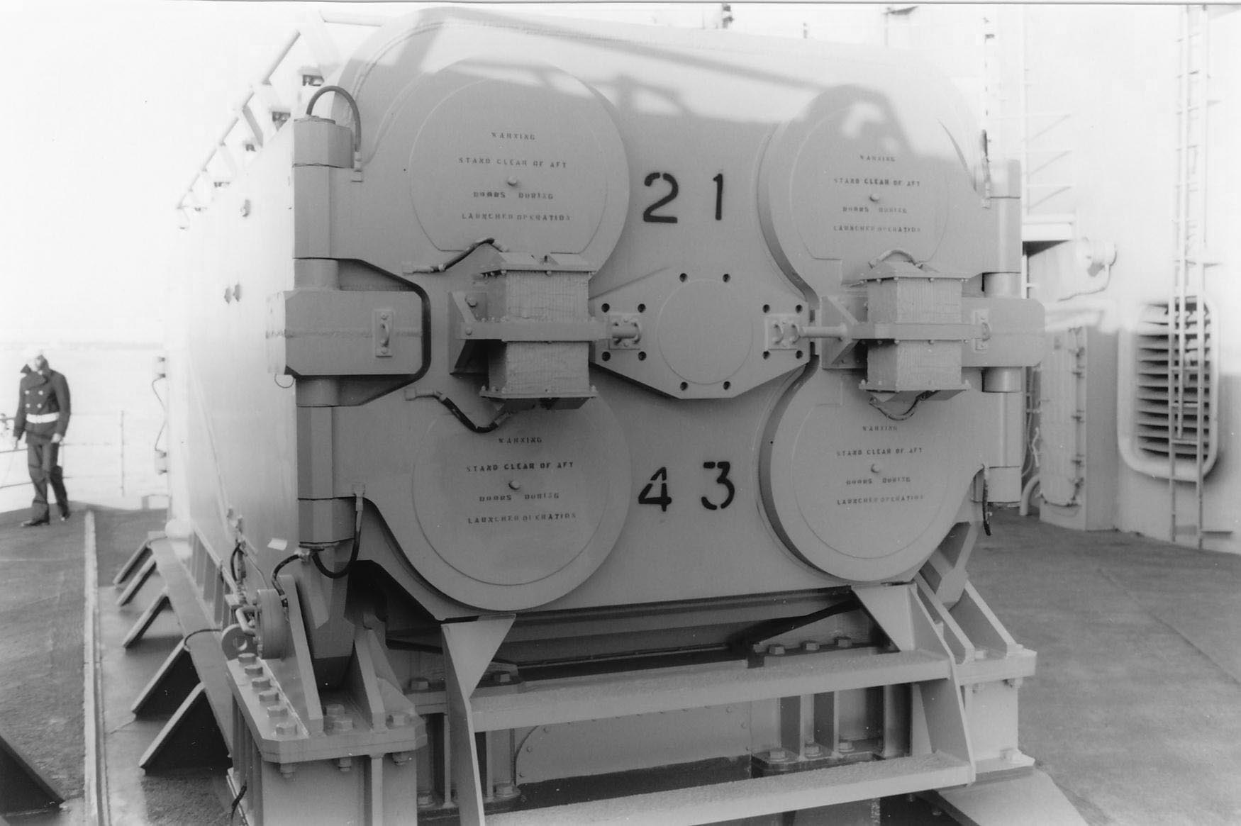
 | 305k | #3 Main Battery Turret of the Iowa (BB-61) in
1985 standing out with just above the armored enclosure for her Mk.53 long-base rangefinder, her new helicopter control station located at the aft end of the 02 level for control and communications during all flight ops; Spot 2 with its MK 13 radar atop, the after MK37 director with MK25 secondary battery radar and new additions like the prominent underway replenishment equipment, a large outrigger for streaming fueling lines to a receiving ship shown in a stowed position with fuel line saddles secured by their whips and the probe secured to an A-frame on her Main Deck. Just behind it, the blast end of a MK 143 Armored Box Launcher for the BGM 109 Tomahawk, and here and an OE-82 dish antenna for a satellite communication relay system on a platform bracketed to the after side of her stack. | USN photo and text courtesy of Pieter Bakels. | |
| Back To US Battleship Construction Index | Back To The Main Photo Index | Back To The Battleship Photo Index Page |
This page is created by Pieter Bakels and Michael Mohl & maintained by Michael Mohl
All Pages © 1996 - 2025, by Paul R. Yarnall NavSource Naval History. All Rights Reserved.