| Click On Image For Full Size Image |
Size | Image Description | Contributed By And/Or Copyright |
|
|---|---|---|---|---|
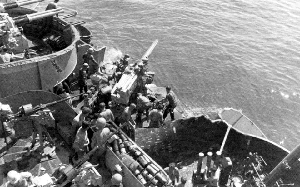 |
90k | Three types of armament are visible - 5in/25cal guns, 40mm Bofors, and 20mm Oerlikons. Note the anti-skid patterns on the deck under the 20mm mounts and the floater net mounted on the 20mm gun tub, January 1945. The 20mm Oerlikon was a free swinging weapon, operated by maximum gas pressure, about 23 tons per square inch and by springs which were correspondingly powerful. Factors such as friction, the effects of different elevations, cold weather, rain were too small in proportion to the operating forces to cause stoppage. Therefore, it offered great reliability because of its reserve of power compared with the Hispano-Suiza gun used before its introduction to the Fleet. It had a high rate of fire and could come into action very quickly. One of the greatest advantages of the Oerlikon was that it had a barrel which could be replaced in about 30 seconds after prolonged fire at sea against multi-plane attacks. It could be bolted down almost anywhere. A talker stood behind the gunner with a loader to his right carrying a spare magazine. The magazine employed with the Oerlikon was superior and could be kept fully loaded without any tension on its springs and feeding the 490RPM was an easy task compared to the Hispano-Suiza magazine which held 690RPM. A canvas bag below the gun took expended cartridge cases. The MK.4 weighed about 1695 lbs and incorporated a feature that permitted the operator to raise or lower the trunnions which often corroded at sea, to accommodate his height. Before the appearance of the Bofors in numbers in 1943, it enjoyed a high percentage of aircraft kills in the Pacific Fleet, 32 percent for the period between Pearl Harbor and September 1944. However, as ranges increased and as the Japanese turned to night attacks, the Bofors and the VT-fuzed 5in guns became more and more significant. Thus, the Oerlikon's share in 1944 amounted to only 25 percent, compared to 48.3 for the second half of 1942. The Fleet demanded more Bofors as it could not defeat an attacker before he released a weapon. It had become a "revenge" gun, only able to prevent him coming home. One Captain reported that the 20mm had a negative psychological effect; "the saying among the crew being that when the 20mm Oerlikons opens fire, it's time to hit the deck". The Oerlikon was retained into the 1950's. |
Text & USN photo submitted by Pieter Bakels. | |
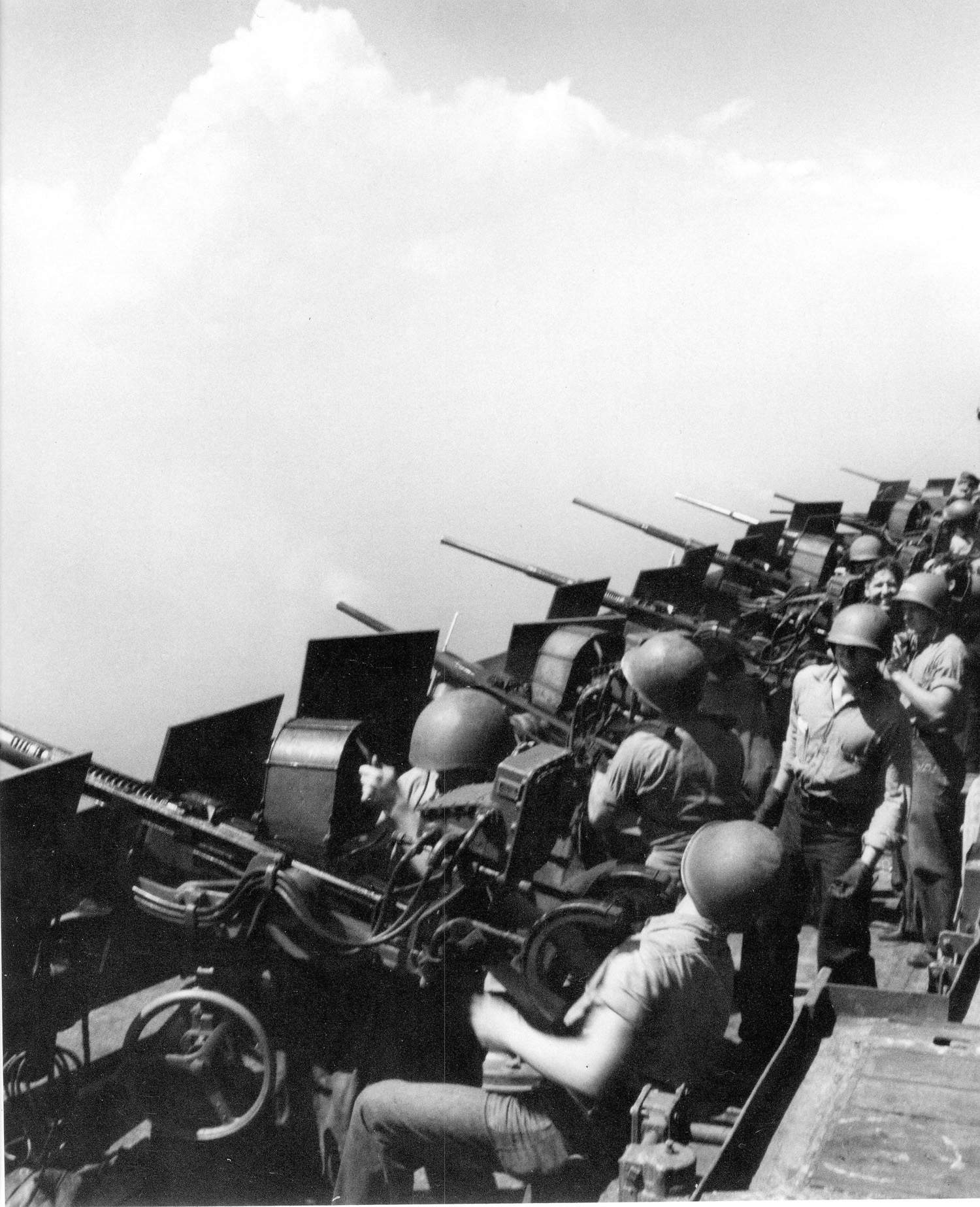 |
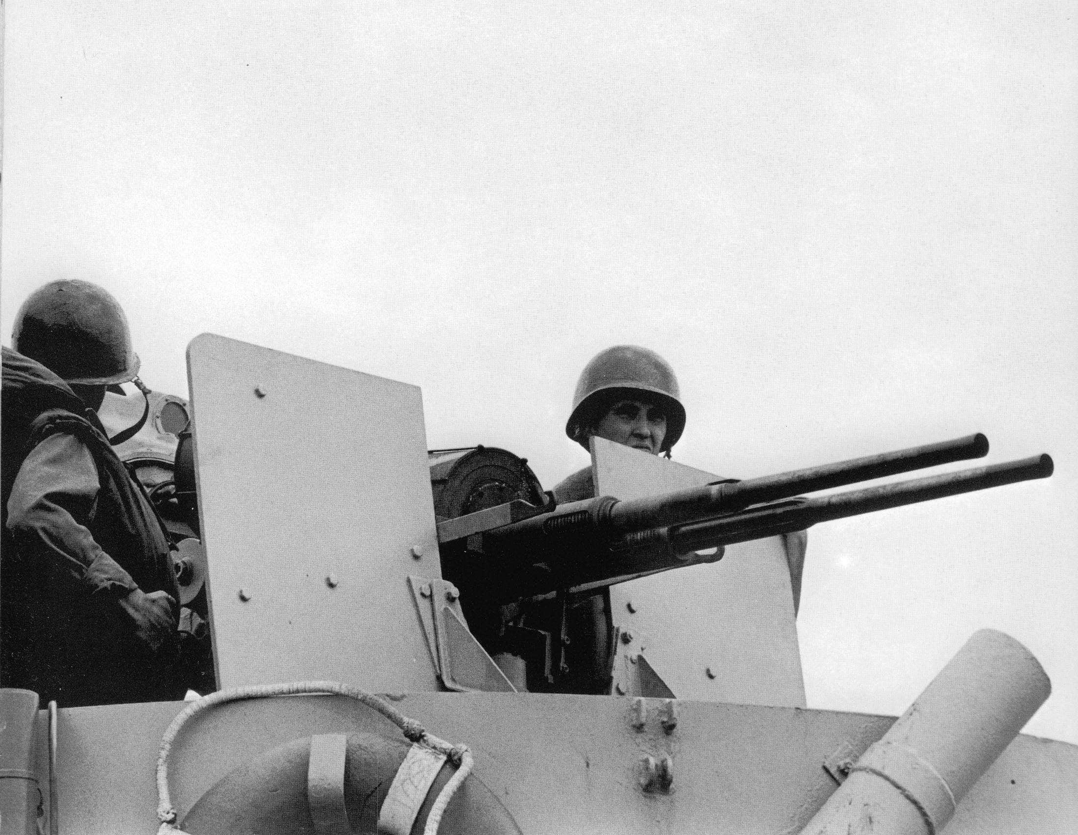
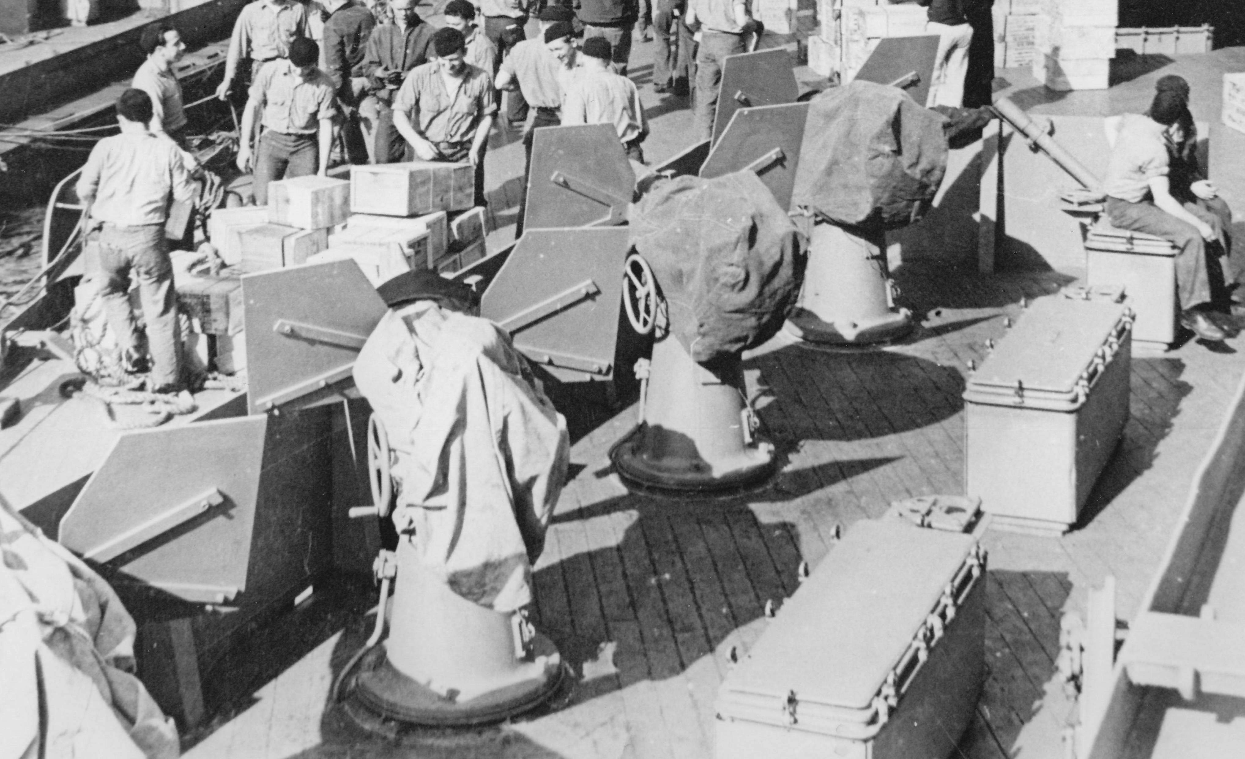
302k | 20mm crews stand by at their stations on February 1945.
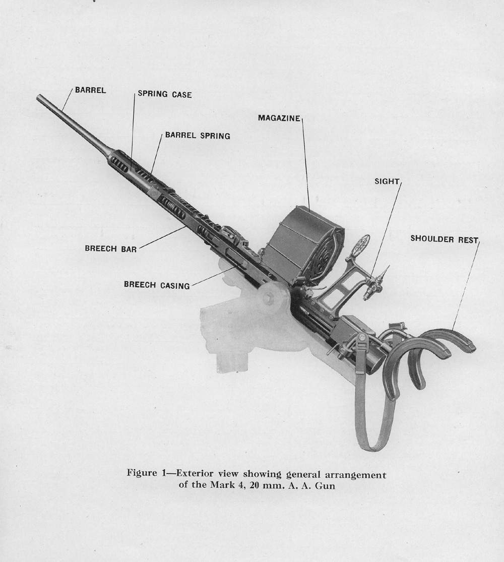
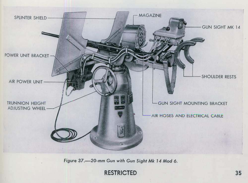
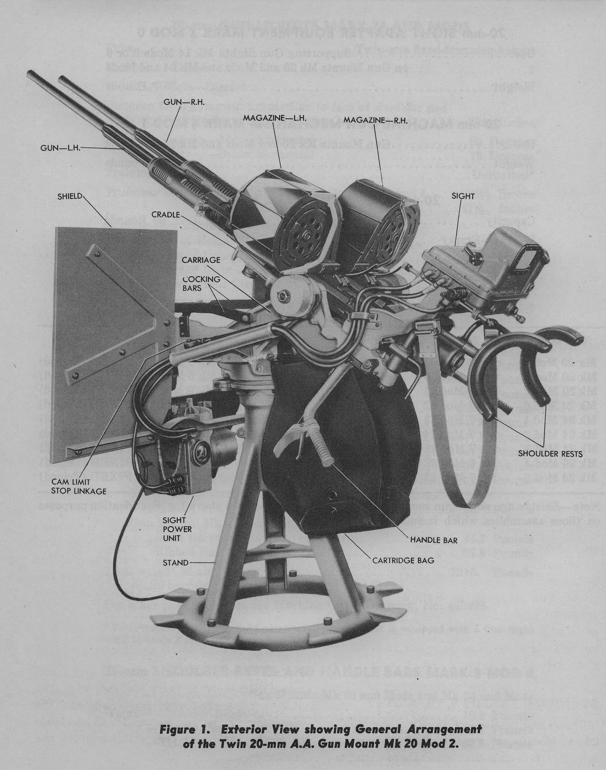
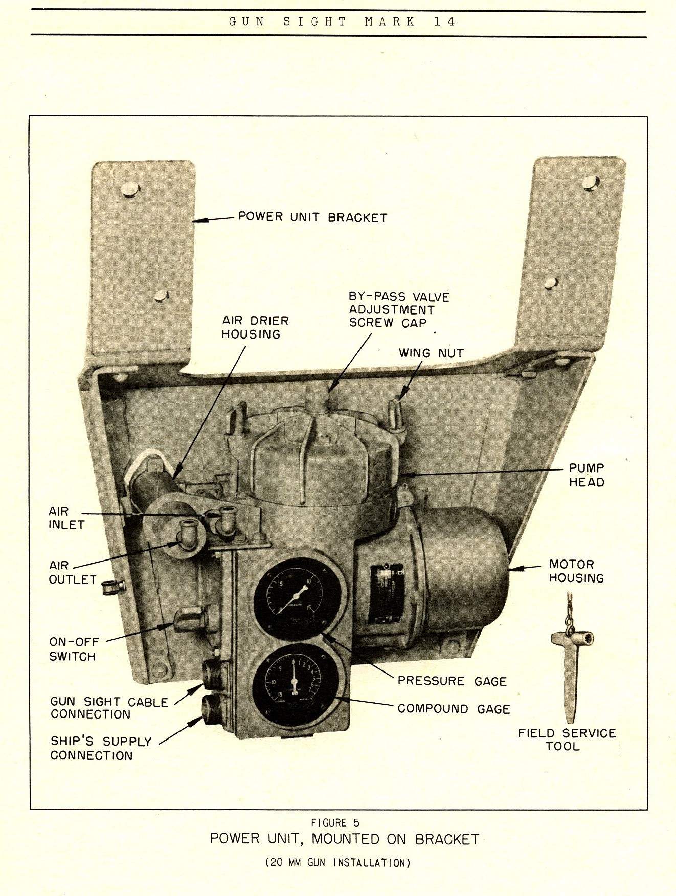
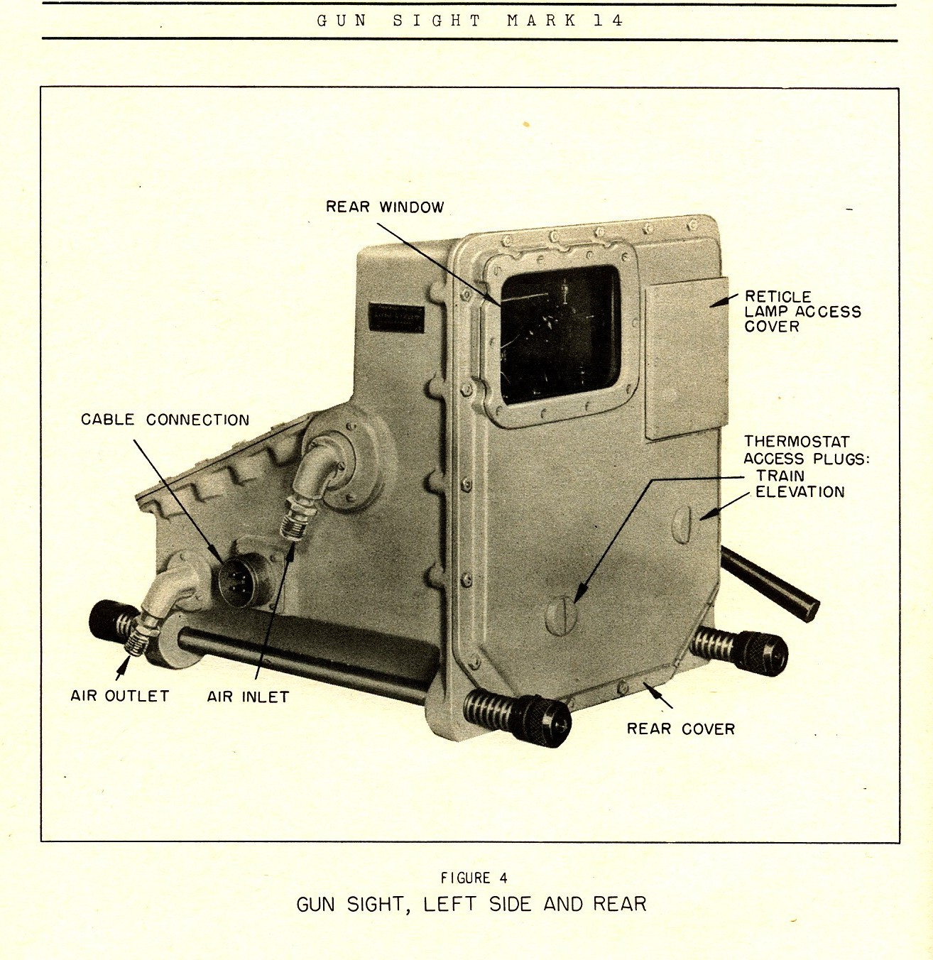
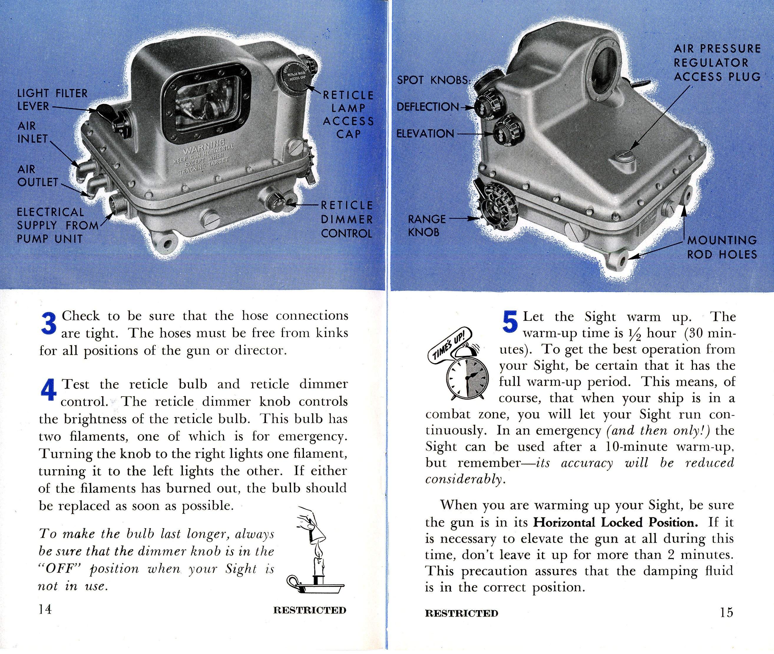
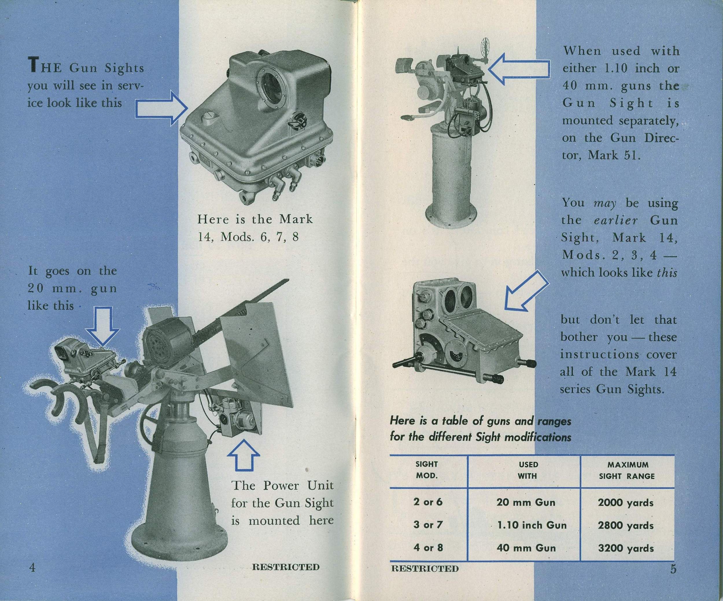
General Description and Characteristics: The gun consists of all that part of the weapon (except the magazine and cradle) that rotates about the trunnion bearing axis. It may be divided conveniently into three sections: 1. The barrel. (Mounted in the breech casing.) 2. The various stops, locking gear, and trigger group (all mounted in the breech casing). 3. Breech block and bolt (including striker pin, breech bars and springs, and barrel spring with casing). The barrel is a forged steel piece approximately four feet ten inches long. It is bored out to a caliber of 20mm (about 0.8 inches). There are nine grooves in the barrel. The outside of the center section has fins that support the barrel springs, holding these springs away from the barrel and permitting air circulation for cooling. The first two inches of the bore flares outward and serves as a flash guard. The breech casing is a steel forging, bored out longitudinally. Its chief functions are: 1. Carry the barrel at its front end. 2. Carry the trigger group at its rear end. 3. Act as a guideway for the breech block in recoil and counter-recoil. 4. Carry the magazine on its top. 5. Attach the gun to the mount. Included in the breech casing are the following: 1. Trigger mechanism-which operates to fire the gun. 2. Recoiling mechanism-which operates in recoil and counter-recoil to introduce the automatic features of machine gun operation. 3. The barrel, barrel stop pin and barrel locking gear. (The latter to stop and lock the barrel in place). 4. Double loading stop-which functions to prevent loading a round of ammunition into the barrel unless the chamber is already clear. The breech block and bolt are included in the recoiling group and contribute to the function of the recoiling mechanism as stated in 2 above. The mount extends from the cradle in which the gun is fixed, to the pedestal bolted to the deck. The cradle rotates about the trunnion axis. The mount permits the height of the gun trunnions to be varied easily and rapidly for any sight angle, to suit the convenience of the gunner. This is done by the column raising handwheel mounted on the pedestal head. Ammunition is supplied to the gun from a detachable mounted magazine, which is filled and serviced while detached from the gun. Characteristics. Elevation limits minus 5° to plus 87° Max. Range (36° elev.) 5,500 yards Weight of gun 141 lbs. Weight of mount 1578 lbs. Weight of magazine loaded 63 lbs. unloaded 31 lbs. Max. LV 2725 ft/sec. Length of recoil 111/z in. Barrel spring pressure at full recoil 534 lbs. General. The 20mm Oerlikon is an automatic, air-cooled, machine gun, with spring recoil and counter-recoil. It will theoretically fire 450 rounds per minute. As ammunition is supplied from a detachable mounted magazine which holds 60 rounds, it only requires about 71/2 seconds to expend one magazine in continuous fire. It is the largest type of automatic gun in use in our Navy which can be operated manually without the use of gears and handwheels. The gun and cradle on the mount are evenly balanced by the use of the cradle spiral spring, which merely counterbalances the additional weight forward. Any attempt to elevate the gun is aided by the pressure of this spring. Horizontally, the weight of the gun, cradle and the mount column, are supported by a series of roller and needle bearings which make possible easy rotation about the vertical axis. Operation and the clearing of stoppages. Principle. The major difference between this gun and others is that the force of the explosion is absorbed in checking and reversing the forward movement of a relatively heavy bolt, or breech block, that is never locked. In most guns the force of the explosion is taken by the locked breech block, and by the recoil cylinders and associated mechanism. The gun fires in AUTOMATIC only, which means that the gun will fire as long as the trigger is pressed and there is ammunition in the magazine. When the last round of each magazine is loaded into the gun the trigger mechanism is returned automatically to the checked position, regardless of the position of the trigger. This feature prevents the breech block mass from counter-recoiling on an empty gun after the last round has fired, and, because there is no explosion to reverse the breech block, a recocking by hand would be necessary before firing could be continued. A Safe/Fire lever is fitted close to the right hand grip. The chief features of the operating principle are as follows: (1) The gun body, including the barrel, does not recoil. (2) The recoiling parts are the breech block and the parts that connect it to a powerful two-piece barrel spring. The breech block recoils and counter-recoils with a purely reciprocating motion. The barrel spring is the only force tending to keep the breech block closed. THERE IS NO POSITIVE LOCK. The following is a brief description of the operation: Preparatory to opening fire, the breech block must be pulled back until the sear is held by the trigger hook. This compresses the barrel springs and causes a pull on the recoiling parts being held in the cocked position by the trigger hook. Pressing the trigger releases the breech block, allowing it to move forward under the pull of the barrel spring. A round of ammunition is picked up from the magazine by the breech block on its way forward and is carried into the barrel. At a point about halfway forward the next round in the magazine forces the cartridge down into the lip of the breech face piece. Just before the breech block reaches the fully forward position, a striker in the breech block is operated by a hammer in the breech block, and fires the round. A hammer plate in the breech casing operates the hammer as the breech block travels on recoil and counter-recoil inside the breech casing. When the round fires, the gas pressure first absorbs the forward momentum of the breech block and then blows the latter backwards, thereby compressing the barrel spring which absorbs the rearward momentum imparted to the breech block by the gas pressure. The breech block is blown backward until at full recoil, it is to the rear of the position at which the trigger hook catches it. As each round fires, the empty cartridges case together with the breech block is blown back from the chamber by gas pressure. Subsequently, the empty case is tripped in the breech casing. The next round in the magazine is forcing the empty cartridge down. When all the rearward motion has been absorbed by the barrel spring, the counter-recoil of the barrel spring forces the breech block forward again. On the way the breech block picks up the next round from the magazine and the firing sequence is continued as long as the trigger is kept pressed or there is ammunition in the magazine. Whenever pressure on the trigger is released the breech block is caught on the next attempt to commence its counter-recoil and is held in the cocked position. This happens in all cases when there is ammunition in the magazine. In case the pressure on the trigger is maintained and the magazine becomes empty, then the trigger is returned automatically to the cocked position regardless of the position of the trigger. The magazine consists of a cylindrical drum containing a clock spring that forces a cartridge feed block around a spiral in the magazine forcing the rounds down into the magazine mouth, where they are picked up by the breech block as it counter-recoils. Stoppages. If the gun stops firing of its own accord, for any reason other than an empty magazine, the following immediate action should be carried out: Put Safety Catch on SAFE and note whether the recoiling parts are in the forward or after position. If the parts are in the forward position, a misfire, a broken striker, a broken hammer or failure to feed the magazine is indicated. Safe precautions for a misfire should be observed. If the magazine is empty and the gun stops in the forward position, it may be due to sticking, or sluggish action of the magazine cartridge feeder bolt which trips the interlock lever. If examination shows that this bolt does not work freely, the magazine should not be used again until the exainination has been corrected. Examine the double loading stop. If the horns are in the down or operating position, there is a round or part of a broken case in the chamber and the mechanism is in the rearward position. Recock the gun and remove the magazine. Examine the chamber and breech face piece. If the lip of the breech face piece is broken off, a new one must be installed. Examine the bore from the muzzle, making sure it is clear. This is necessary to avoid a premature or bulged barrel. An ejector tool is provided in the tool roll to remove any H.E. shell and practice shell left in the bore. This ejector should be used gently, and if excessive resistance is felt when removing a H.E. shell, then change the barrel. Ammunition should be thoroughly examined before loading magazines for hair or dirt which should be removed. If the grease coating is disturbed by this process it should be replaced before loading the ammunition into the magazines. All 2Omm ANTI-AIRCRAFT AMMUNITION MUST BE COMPLETELY COATED WITH A COAT OF ''LIGHT GREASE BEFORE BEING LOADED INTO THE MAGAZINE. Dry ammunition or ammunition with insufficient grease will jam in the gun chamber when fired, and extraction will be very difficult or even impossible. Duties of Members of the Gun Crew The gun crew of the 20mm gun consists of three men normally; four men when the gun is quipped with the Mark 14 gun sight. GUNNER - In charge of the gun. Takes station in the straps, aims and fires the gun. LOADER – Responsible for the service of the ammunition to the gun, removing and replacing magazines. COLUMN OPERATOR - Watches the gunner and operates the column raising handwheel to maintain gun trunnion height at the best position for the gunner. SIGHTSETTER - Mans the 10, 11, 12, or 13JY telephones and keeps the range set according to orders or dOctober rine. Makes elevation and deflection spots. NOTE - If the gun is not equipped with a Mark 14 sight the gunner will man the JY telephone. DETAILED DUTIES OF THE VARIOUS MEMBERS OF THE CREW WILL BE FOUND UNDER "STANDARD COMMANDS FOR THE 20MM BATTERY". Ammunition There are seven types of ammunition as described below ; 1. High Explosive with tracer - PETN loaded - Color BLUE. 2. Same as 1 above except TETRYL loaded - color LIGHT GRAY. 3. H.E. (PENTOLITE) without tracer –color YELLOW. 4. Same as 3 above except loaded with TETI.YL -color WHITE. 5. Blind loaded and tracer-DARK GREEN GRAY with YELLOW BAND. 6. Blind loaded and plugged - DARK GREEN GRAY. 7. Incendiary - color RED. South Dakota (BB-57) present (1944) service allowance contains only types 1, 2, 6 and 7 above. The projectile has about one half the cavity loaded with pyrotechnic tracer mixture designed to burn in about 33/4 seconds. The forward part of the cavity is loaded with pressed TETRYL. The fuseused is a simple air-column type with no moving parts. Its action is initiated by impact, either head on or glancing. The closing disc, being displaced into the fusebody on impact, an air column is instantaneously compressed and wiredrawn through an inner disc. The rate of pressuretemperature rise is sufficient to ignite the load inside, which in turn ignites pressed TETRYL in the detonator, and ignition of the burster charge is effected. The fuseis designed definitely not to function on the equivalent of 0.012 in. duraluminum plate (or lighter), but definitely designed to function on the equivalent of one-eighth in. steel plate or heavier. The fuseis not equipped with any bore-safe feature, and will act whenever the closing disc is displaced into the fusewith sufficient force. The projectile is not equipped with a self-destructive feature. FOR THE ABOVE REASON - NEVER FIRE AN H.E. SHELL THROUGH A MUZZLE COVER. To prevent this, the last two rounds loaded into the magazine will be blind loaded. The Care and Preservation of the Gun and Mount. The 20mm Oerlikon gun is one of the most rugged machine guns ever built. It has only a few moving parts and if these parts and the barrel are given a small amount of care the gun will always be ready to fire, and few difficulties will develop. Its action is different from that of other guns, and so is its upkeep. The cleaning and oiling of the gun should be carried out as required and not at any fixed interval. Being exposed to the elements most of the time, the need for overhaul will vary with the weather and sea conditions. It should be realized that in this type of gun the force of the explosion is utilized in checking and reversing the forward movement of a relatively heavy bolt that is never locked. The proper functioning of the gun depends on the free movement of the recoiling parts, and on the free operation of the various springs used. Any dirt, corrosion, or lack of lubrication present to a degree that will impede free movement and free operation will cause stoppages during firing. It will be the duty of every gun crew coming on watch to insure that the proper measures have been taken to maintain the gun ready to fire on an instant's notice. This will be in addition to regular daily routine which will be carried out by the Gunner's Mates. This routine will be in accordance with the daily and weekly check-off sheets for the 20mm battery. Breaking down and overhaul of the Mark 4 mount is a major job and will be done only when absolutely necessary, and the Air Defense Officer has given permission to undertake the job. Special Safety Precautions for the 20mm Gun. 1. NEVER FIRE AN H.E. SHELL THROUGH A MUZZLE COVER. 2. See that the last two rounds loaded into each magazine are blind loaded. 3. DO NOT FIRE IF THE BORE IS FILLED WITH WATER, EITHER FROM NEAR BOMB MISSES OR SHIPPING SEAS. THIS WILL PROBABLY SPLIT THE BARREL. 4. MISFIRE - The 20mm gun is unique in that no second attempt should be made to fire. Procedure on misfire is as follows: If it is found that a projectile is lodged in the bore, the ejector tool and cleaning rod should be inserted from the muzzle end and the projectile backed out and tossed overboard. PERSONNEL SHOULD KEEP CLEAR OF THE BREECH, AND THE MAN HANDLING THE EJECTOR TOOL SHOULD AVOID GETTING IN LINE WITHE THE BORE. Use only pressure or a light blow to dislodge projectiles. If no water is available, the breech block should be withdrawn sufficiently to establish the fact that a round is in the barrel. If there is, CLOSE THE BREECH IMMEDIATELY. Lock gun in train and elevation in a safe position and stand clear. IN ACTION – The use of the ejector tool at once is the only thing. Under action conditions, when a misfire occurs, take the following action immediately. OPEN BREECH, INSERT EJECTOR TOOL IN THE MUZZLE AND DRIVE THE PROJECTILE (if any) OUT OF THE BORE. DO NOT FIRST LOOK INTO THE BORE TO SEE IF IT IS CLEAR. If no projectile is in the bore. no harm has been done. If there is a projectile in the bore, THERE MAY ONLY BE ABOUT A MINUTE TO REMOVE IT BEFORE THE GUN EXPLODES. THE MARK 14 SIGHT The Mark 14 sight is especially designed to direct the fire of automatic weapons on rapid moving targets at short ranges, that is, aeroplanes and torpedo boats. It can also be used to fire at fixed and semi-fixed targets. Because it needs no stabilized reference plane, it is easily adapted for use aboard ship. As long as the operator tracks the target with a smooth track, there are no affects of rolling and pitching on the sight. The principle of the sight is based on two air-driven gyro units, one gyro being set in the horizontal plane with respect to the gun bore axis, and the other gyro being set in the vertical plane of the gun axis. As the sight is firmly fixed to the gun cradle, these gyros precess as the gun is moved. The gyros position two mirrors, one a silver backed mirror, (train) and one a clear glass mirror, (elevation), through a series of shafts, gears, and gimbals. On these mirrors is reflected an illuminated reticle, corresponding the cross wires in a conventional telescope. As the target moves, the operator moves the gun so as to hold the reticle on the target. As the gun moves, it exerts a force on the gyros, causing them to precess. As the gyros precess, they further position the mirrors, thus causing the position of the reticle to change on the mirrors. Hence a lead angle is generated between the line of sight and the line of fire, and this angle is correlated with the speed and the direction of movement of the target. The gyros, mirrors, and various air filter and heater units to be discussed later, are enclosed in the sight box. On the right side of the sight box is found the rheostat controlling the brilliance of the reticle, an elevation spotting knob, a deflection spotting knob, and a range handle. Attached to the splinter shield of the mount is the power unit composed of an electric motor, an air pump, air intake and outlet tubes, air drier unit, a pressure gauge and 4 g compound gauge. This power unit supplies the sight with the air pressure with which the gyro units are driven. In addition a transformer is enclosed in the housing of the compressor, transforming ship's 115 volt current to 10 volt current with which the reticle lamp is lighted, and also supplies 115 volt current to run the heaters and thermostats in the sight box. The air hoses and electric cables run from the power unit to the left side of the sight box. THE FIRE CONTROL PROBLEM Effects of target velocity and of gravity must be considered in directing the fire of automatic weapons against rapid moving targets at ranges closer than 3200 yards. Other ballistic effects such as wind and drift can be considered negligible. A gun is fired at an airplane. At the instant of firing the plane is at a position called the present position. The gun should be pointed at some later position of the target, known as the future position, so that when the projectile reaches the future position, the target will be there. The angle formed by lines to gun-present position and gun future position is known as the lead angle. The angular velocity of the target, (as observed by the angular movement of the target about the gun), per second, times the time of flight of the projectile (or the time which is necessary for the projectile to reach the target), gives the lead angle. If the gun is pointed at the future position of the target, the projectile will fall short due to the force of gravity on the projectile. Hence gun elevation is increased by an additional angle to compensate for this force. This angle is known as the angle of super-elevation. THE FUNCTIONING OF THE SIGHT The sight consists of five interconnected systems: 1. Optical system. 2. Gyro system. 3. Range adjustment system. 4. Air supply system. 5. Temperature control system. 1. Optical system: The optical system supplies a sighting reference for the gunner. This reference can be offset from the parallelism of the gun bore, and is known as the illuminated reticle. This illuminated reticle is derived from the reticle lamp, corresponding to an automatic headlight bulb, and the current is of 10 volts, supplied from the transformer in the power unit. The brilliance of the illuminated reticle is controlled by a rheostat knob, located on the right side of the sight case. The reticle lamp shines through the reticle box, and hence through a collimating lens. The lens focuses the reticle onto the mirrors, so that it is in focus at all distances farther than a few feet - away from the sight. The reticle box is positioned by two cams, and can be moved in two directions. These cams work from the elevation and deflection spotting knobs, on the right side of the sight case, and are connected to the spotting knobs by shafts and worm dears. After the light passes through the collimating lens, it is focused onto an aluminized mirror, known as the train mirror. This mirror is pivoted around an axis parallel to the gun bore. The light is reflected from the train mirror to a clear glass mirror known as the-elevation mirror. Clear glass is used so as to allow the gunner to observe the target by direct vision and the reticle by reflection simultaneously. The elevation mirror is pivoted around an axis perpendicular to the axis of the train mirror. If the mirrors are properly bore-sighted, both mirrors will make angles of 45 degrees with the light from the reticle when the gun is stationary. Angular displacement of the train mirror will cause the reticle image to move parallel to the elevation mirror axis. Angular displacement of the elevation mirror will cause the reticle image to move perpendicular to the elevation mirror axis. In order to hold down vibrations, dampers are placed on each mirror; these dampers being similar to those dampers on the gyro units to be discussed later. Fixed spots can be applied to the sight by positioning the reticle box. In moving the reticle box to the left or right, the illuminated reticle is moved to the left or right on the train mirror. The reflected light, therefore, is moved up or down on the elevation mirror, and hence a spot in elevation or depression is applied. If the reticle box is moved up or down, through the same series of events a spot in left or right deflection is applied. Therefore, the elevation spotting knob moves the reticle box to the left and right, and the deflection spotting knob moves the reticle box up and down. The maximum movement is plus or minus 25 mils in both train and elevation. 2. The gyro system: The gyro system consists of two gyro units already mentioned, one in train and one in elevation. These units pick up the angular velocity components imparted to the gun by tracking the target. Each gyro consists of a wheel mounted in ball bearings which are supported by a gimbal frame. The gimbal frame is held in the gyro housing by a frictionless spring suspension. Attached to the gimbal frames are two discs, which fit into housings containing a damping fluid. This damping fluid reduces vibration and smoothes the action of the gyros. When the train axis of the gun is vertical, and the gun bore is horizontal, the spin axis of the train gyro unit is horizontal. At the same time the spin axis of the elevation gyro unit is vertical. Both spin axis are perpendicular to the gun bore. The train gyro unit controls the angular position of the train mirror by means of the train gyro crank. This crank is firmly attached to the gyro gimbal frame. At the outer end of the train GYRO crank is a fork which engages a ball attached to the train MIRROR crank. The only difference between the mechanical drive for the elevation mirror and the train mirror is in the elevation mirror bell crank. This bell crank is placed in the system so as to permit operation of the elevation mirror about an axis perpendicular to the elevation gyro axis. The above arrangement moves the mirrors in such a fashion that the lead angles in train and elevation as indicated by the reticle are proportional to the precession of the gyro units, in train and elevation respectively. Under THE FIRE CONTROL PROBLEM, it was brought out that the angle of super-elevation must be considered. This is done through weights threaded onto the balance arm of the gimbal frame, and are known as super-elevation weights. These weights are applied to both the train and elevation gyro units. The super-elevation weight applied to the elevation unit is threaded onto the side of the balance arm. Consequently, when the gun bore is horizontal, the deflection of the elevation gyro, caused by this weight, is at its maximum. As the gun is elevated, the effect of the weight diminishes, finally becoming a zero component when the gun is elevated at its zenith. In the train gyro unit, the weight is threaded onto the top of the balance arm. When the gun bore is horizontal, this weight has a zero component, but as the gun is trained, and the gyro precesses, the component of the weight is proportional to the amount of precession. The gyros are so placed so as to interchange functions if the sight is tilted away from the vertical about a line parallel to the gun bore. 3. Range adjustment: The gyros that have been discussed to date (1944) are restricted, in that the angle of tilt is in one plane only. The plane in which the elevation gyro can tilt (or precess) is the horizontal, and that of the train gyro is vertical. Further restrictions can be applied to these units in that the amount of precession can be controlled. According to the law of precession, the amount of "tilt" will be directly proportional to the applied force. At greater ranges, the angle of lead will be greater due to the increased time of flight of the projectile and the additional effects of gravity (consequently a greater angle of superelevation). At shorter ranges, this angle of lead need not be as great since the time of flight of the projectile is shorter, and the speed and force of the projectile overcomes the force of gravity. It is necessary to vary the amount of precession allowable where at shorter ranges a greater force is being applied to the gyros through the gun, and at the same time a shorter lead angle is necessary. This is done through a variable restriction on the gyros. These restrictions can be increased or decreased by moving the range handle on the right side of the sight. This range handle, through a shaft and worm gears, position sets of cantilever springs. In the train gyro unit, these springs embrace a knife edge, this knife edge being rigidly attached to the gimbal shaft of the gyro. In the elevation gyro unit, these springs are beneath the knife edges, one knife edge on each side of the unit and rigidly attached to the gimbal shaft. By increasing the distance from the knife edges to the fulcrums of these springs (where they are attached), the restriction on the gyro units is decreased. Likewise in decreasing the distance from the knife edges to the fulcrums, the restrictions on the units is increased. As the spring force decreases, the force necessary to precess the units is decreased, and the angle of precession is increased. The opposite applies when the spring force is increased. As has been pointed out before, at greater ranges, the restriction on the gyros must decrease. Consequently the range scale on the right side of the sight case is so set that when the minimum restriction is being applied to the gyros, the range handle is pointed tc the maximum range setting, that is, 2,000 yards. Likewise when the maximum restriction is being applied to the gyros, the range handle points to the minimum range setting, or 400 yards. 4. Air supply system: The function of the air supply is to furnish clean dry air of about seven pounds per square inch pressure, and of proper air temperature to the gyro nozzles. The air passes into the power unit through the air intake and passes through a filter, which removes all traces of foreign matter, dirt, or moisture. From the filter the air passes over a heater unit which brings the temperature to approximately that of the gyro units. Then it passes through a pressure regulator which eliminates effects of supply pressure variations. From the regulator the air passes by a thermostat which controls the air heater. In this way a constant air temperature is maintained. From the thermostat a supply tube leads to each of the gyro units. In the base of the sight case is an air intake valve which allows air to be brought in when the vacuum inside the case exceeds its normal pressure. The compound gauge should be 0.7 at all times when the sight is running. The air pressure gauge should read between 6 to 8 pounds pressure when the sight is running. 5. Temperature control system: Constant temperature of the damping fluid in the gyro units is maintained by heaters fastened to the damping disc housings and controlled by two thermostats. For proper functioning of the sight it is necessary that the damping fluid be at a specified temperature at all times. The sight case is insulated so as to prevent external temperature variations. HOW TO USE THE SIGHT, FOLLOWING THE LIGHT MACHINE GUN DOctober RINE Turn the sight motor on, so as to build up the air pressure. Some power units have a system by which the air heaters and thermostats are working continuously. In these cases, approximately five minutes is all that is necessary to allow the sight to warm up. In the event that the sight has no such attachment, allow twenty to thirty minutes for the sight to warm up before using it. When slewing onto a target, have a minimum range setting applied on the range handle, so as to prevent the gyros from precessing too far, and therefore causing a delay in steadying the reticle on the target. When the gunner has the reticle on the target and begins his track, set the range handle on 1,200 yards if the taiget is at 1,200 yards or beyond. As, the target approaches and comes within the 1,200 yard range, set the range handle down one detent to 800 yards. 800 yards is the minimum range setting used on Mark 14 sights aboard the South Dakota and 1,200 yards is the maximum setting. Spotting with the elevation and deflection spotting knobs is discouraged since most spots can be applied with the range handle. Any such spots with these knobs should be referred to the Sector Control Officer of that sector. When securing the sight, have a maximum range setting applied, so as to prevent any weakening of the various springs. |
Text & USN photo submitted by Pieter Bakels. | |
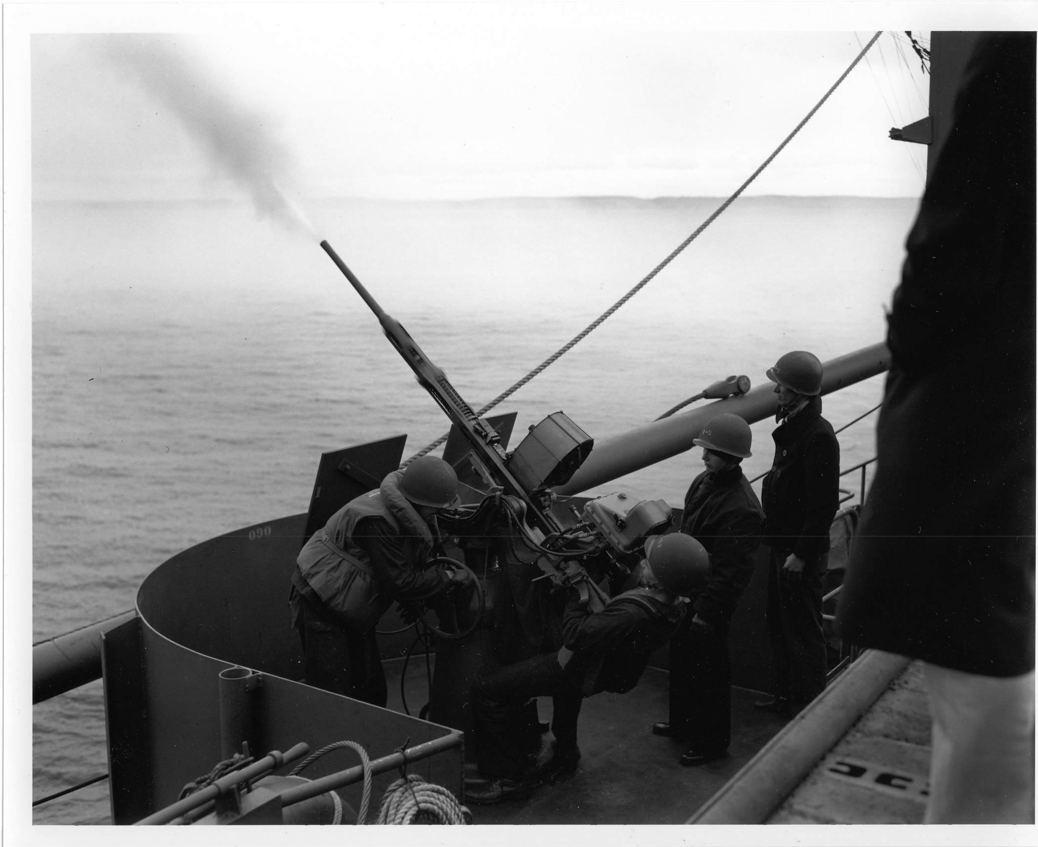 |
188k | 20mm firing. Note the gun shield does not yet have the cutout for gun sight Mk.14.Mod.6. | USN photo submitted by Pieter Bakels. | |
 |
662k | The 20mm AA gun & crew, from "The Blue Jackets's Manual", 1944. Shown here is a PDF for operating instructions for the 20mm Gunsight. |
Text & USN photo submitted by Pieter Bakels. | |
 |
662k | Sailors man 20mm guns during an operation. Note the Gunsight Mk.14 Mod.6 atop gun mount. In 1943 the Bureau of Ordnance received reports that it had become common practice aboard ship to secure the 20mm guns located at maximum level. It had been observed that on MK.14 Gun Sights returned for repair, that in several cases the mirror damping fluid had run out of the train mirror damping housing over the hub and bearing. In view of that observation, and also of the fact that the gyro assembly and calibration the units were carefully preheated in the normal position to correctly distribute the damping fluid- it was recommended that the ship secure 20mm guns on which the MK.14 Gun Sights were mounted in near level rather than high-elevation positions. South Dakota's gunners (About ten years ago I discussed this with one of them) expressed doubts on the worthlessness of a lead computing sight (MK.14). The Bureau's general appraisal was that those comments were generally based on a short-sided view of the entire problem of automatic weapon control, or perhaps nothing deeper than an aversion to the "new-fanged gadgets". It recalled that 25 years earlier or so, there were skeptics who felt that the gyro compass was an unnecessary complicated means of doing a job which was done well enough by the magnetic compass. THAT opinion had been much nearer to being right than the one which held that the old-fashioned way of using a machine gun like a hose was still good enough, for the magnetic compass at least could do a complete job, where tracer control of machine gun fire was limited by the physiological features of the human sighting apparatus which fails in depth perception beyond 500 yards. One especially enlightening comment heard by the Bureau- enlightening in the sense of revealing a basic misunderstanding of the material- was to the effect that the MK.51 director was an excellent device but the MK.14 sight was no good. Inasmuch as the lead-computing element of the MK.51 director was no other than the MK.14 sight, the Bureau could not attach much weight to the appraisals expressed in those comments. One adverse comment that bore thoughtful consideration, however, was that the MK.14 sight took an appreciable length of time to steady down, whereas with tracer control, fire could be opened instantly. (As late as 1991, a Dutch Navy (20mm Oerlikon) gunner repeated that same view!) This view overlooked the fact that although fire could be OPENED instantly with tracer control, real control could not in fact be exercised until the stream of fire had reached the target. And discounting the highly improbable chance that the fire was "on" to begin with, effective fire would not result until some time after the first bullets had passed the target. The time taken by the MK.14 sight to steady down was also approximately equal to the time of flight to the target. It followed that effective fire would result earlier with MK.14 sight control than with tracer control, and moreover, that the expenditure of a considerable portion of the magazine, for what were in effect mere spotting shots, could be avoided, the entire magazine thus being available for effective fire. Another questionable comment heard was to the effect that the lead computing sights were unnecessary for 20mm guns mounted because attacks were chiefly no-deflection shots. This might be reasonable true if one considered only dive-bombing and only those guns near the part of the ship being dived on, but actually very appreciable deflection, components, both vertical and horizontal, would exist more often than not in a ship as long as a BB. With respect to the assumption that the MK.14 sights were fragile, it had to be born in mind that in its development, it had been subject to many tests to prove its resistance not only to vibration and shock but also to exposure well beyond the degree to which it had been likely to be subjected in any reasonable normal service. Of considerable concern to the Bureau was the tendency noted in "some quarters" to jump to the conclusion based on reports of operators who were either untrained in the use of the sight or who had limited experience with it. The latter may themselves have been prejudiced by hearsay from 'battle-seasoned" gunners who "fought it out with the enemy without sights and who felt that had been good enough the last time, would be good enough the next time"... A vicious philosophy, in as much as the enemy could be expected to seek ways and means to overcome the factors that had in the past defeated him (!!!) In the case in question that meant tracer-controlled fire had thus far been able to do an effective job, but the enemy would develop tactics based on greater ranges. To meet this inevitable development, close-in weapons had to be prepared to do at 1200-1500 yards the job they had been doing at perhaps 300-800 yards. Results of years of practice under relatively ideal conditions had demonstrated before that at ranges as great as 1200 yards, the effectiveness of tracer-controlled machine gun fire had been practically nil. A gunner who approached the MK.14 sight with the notion that it was "no good" would no doubt confirm that notion in his mind, for the sight required intelligent use and a realization that the operator himself contributed importantly to the result... A gunner who did not understand what this sight was supposed to accomplish, could completely defeat the purposes of the sight. The Bureau invited the attention of gunnery officers to the need for ensuring that their machine gunners did understand the principles and operating techniques of this sight in order to extract from it its potential worth. |
Text & photo added 04/02/10. USN photo submitted by Pieter Bakels. | |
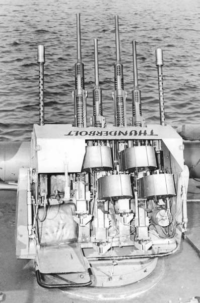 |
45k | The version on the above image,(Prototype Elco Thunderbolt with two 0.50-caliber machine guns and four 20mm in late 1942) the ELCO quad, a quadruple 20mm (Oerlikon), power-driven mount originally intended for PT boats (Mark 15) did not have the later Mark 14 lead-computing sight (see G.A. drawings given) that enhanced its A.A. capability but had a simple tube sight above the operator's seat.
The "Thunderbolt" was an attempt to increase 20mm hitting power. At night, the continuous stream of tracers from the "Thunderbolt" gun, like the beam of a searchlight, hurled destructive 20mm projectiles at 1800 rounds per minute at an enemy. Designed as a dual-purpose weapon, it had an elevation/depression range of +85/-15 degrees and full traverse. Two units were mounted on the Massachusetts (BB-59) and Maryland (BB-46) to augment their batteries and retained the Mark 14 gun sight. By June 1944 it had been authorized also for Arkansas (BB-33), Colorado (BB-45), West Virginia (BB-48) and Washington (BB-56) and the training ship Wyoming (AG-17). The Pacific Fleet recommended further installations in view of the success of the first two but nothing came of the project, partly because BuOrd considered the 20mm most valuable as a free-swinging weapon which could still be used after all shipboard power had been lost. The mount consisted of a quadrant-shaped armoured gondola with four guns. The gondala sides and back were constructed of 1/4in plate with a 1/2in front plate. A tubular handle was attached to the rear of the gondola which permitted manual elevation and traverse of the mount in the event of an electric or hydraulic failure. It had a gunner's seat with joystick and firing treadle fitted to port. An oil filter and recuperator were fitted to starboard. There were slots for shell ejection and manual cocking of the 20mm cut in the rear. The gondola pivoted on two vertical yokes wit elevation and depression effected by an hydraulic ram on each yoke. The yokes were attached to a conical base which contained an electrically-driven hydraulic traversing motor. Installation of the mount required the addition of a 24-volt DC generator. The "Thunderbolt" weighed about the same (560lb) as the more powerful 40mm (single) mount. |
Text & USN photo submitted by Pieter Bakels. | |
| Back To US Battleship Construction Index | Back To The Main Photo Index | Back To The Battleship Photo Index Page |
This page is created by Pieter Bakels and Michael Mohl & maintained by Michael Mohl
All Pages © 1996 - 2025, by Paul R. Yarnall NavSource Naval History. All Rights Reserved.