NavSource Online: Battleship Photo Archive
Interior Communications
To Additional Pages
Battle Telephone Communications
| Click On Image For Full Size Image |
Size | Image Description | Contributed By And/Or Copyright |
|
|---|---|---|---|---|
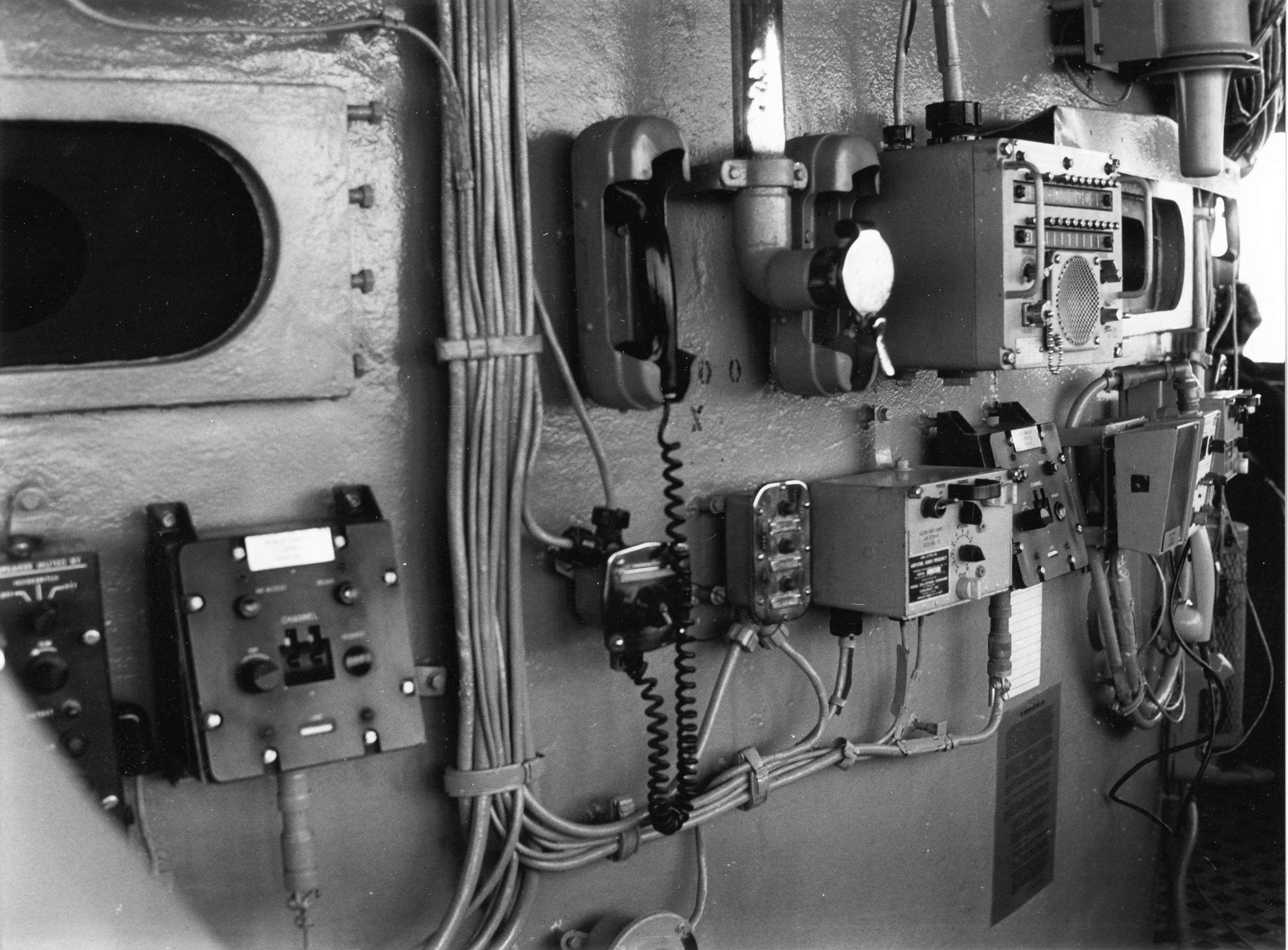 |
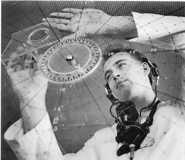
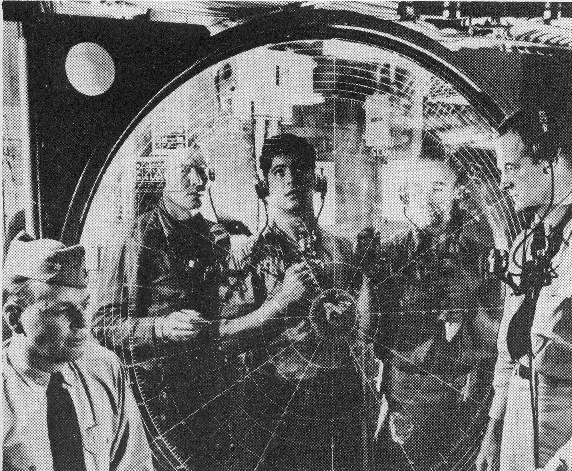
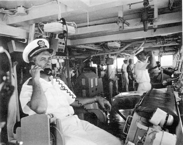
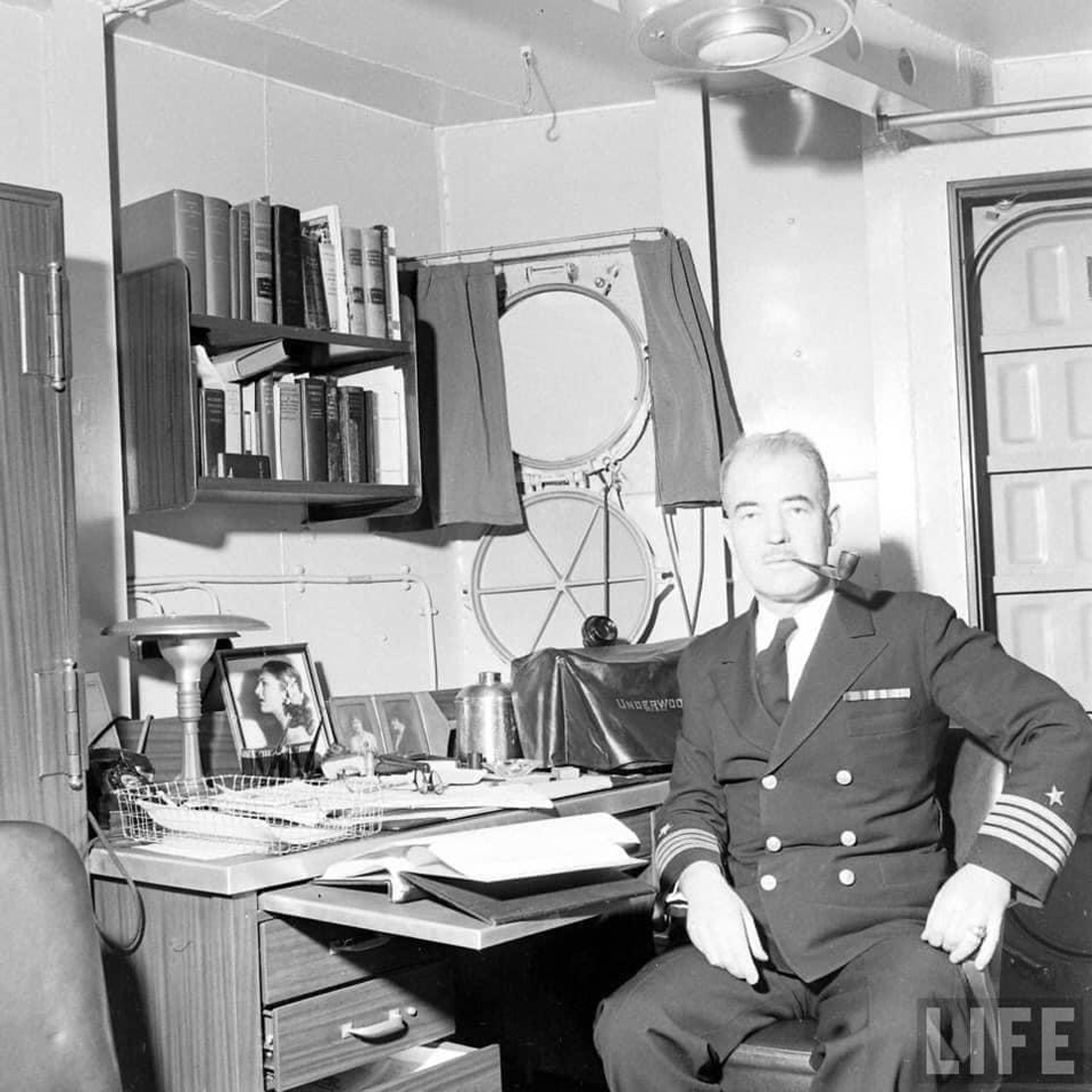
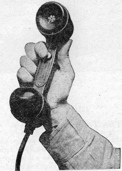
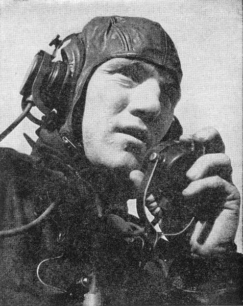
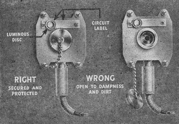
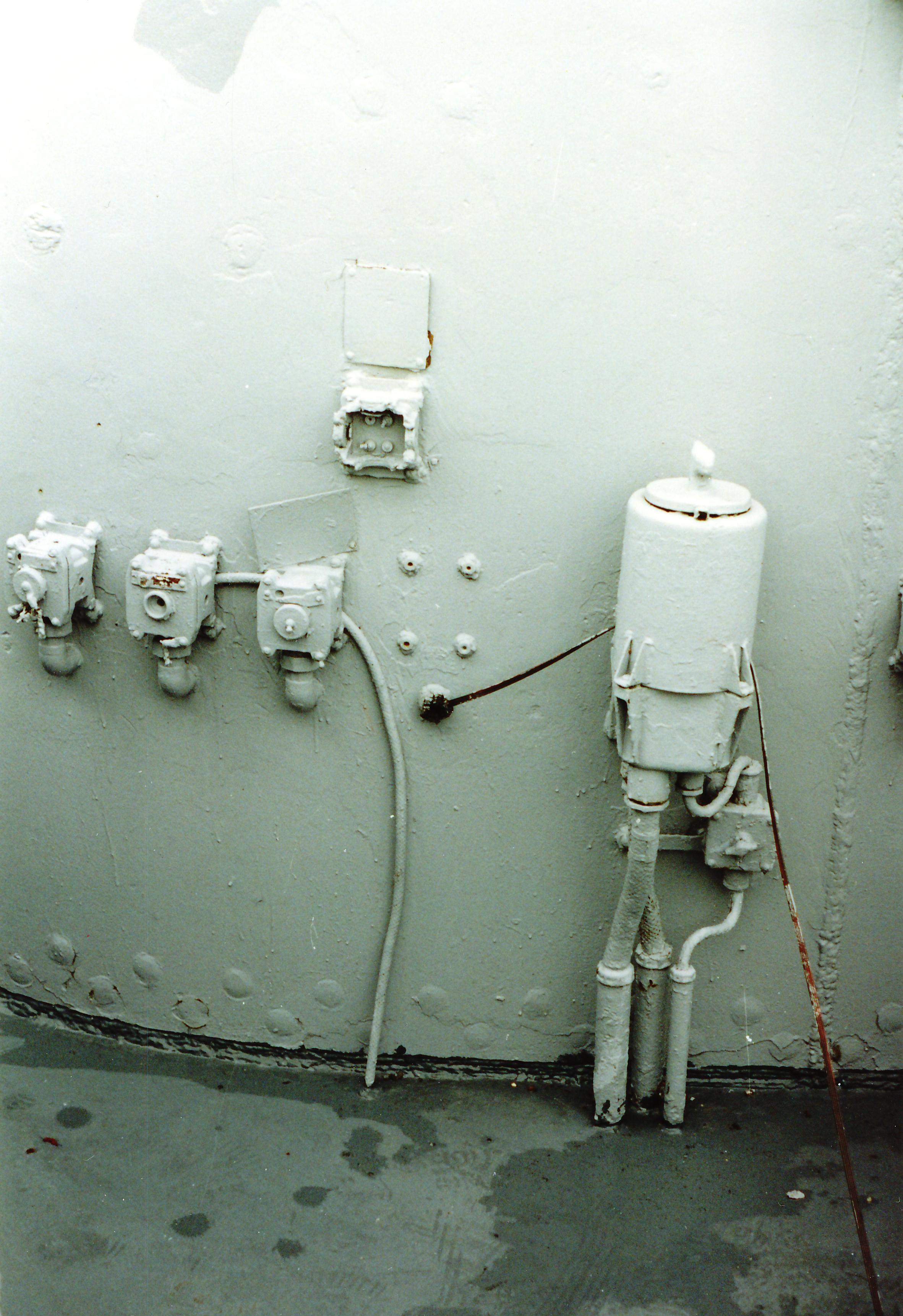
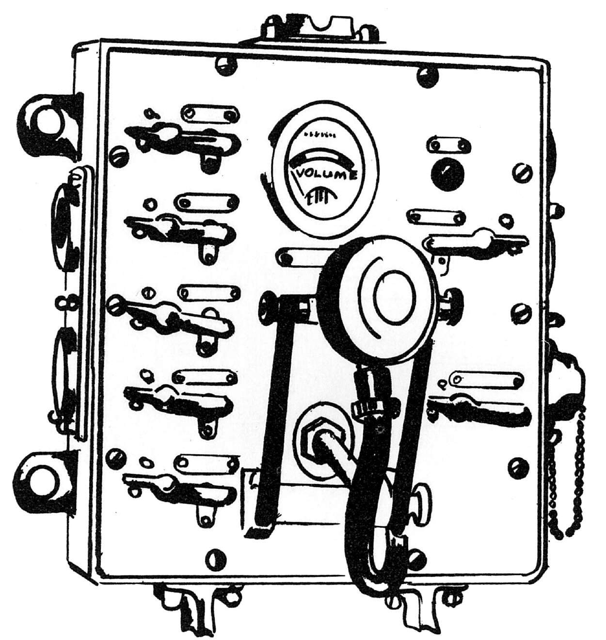
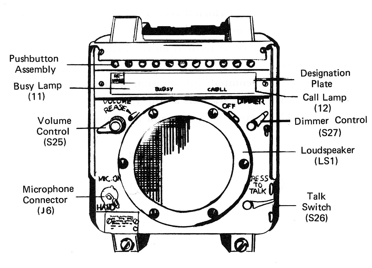
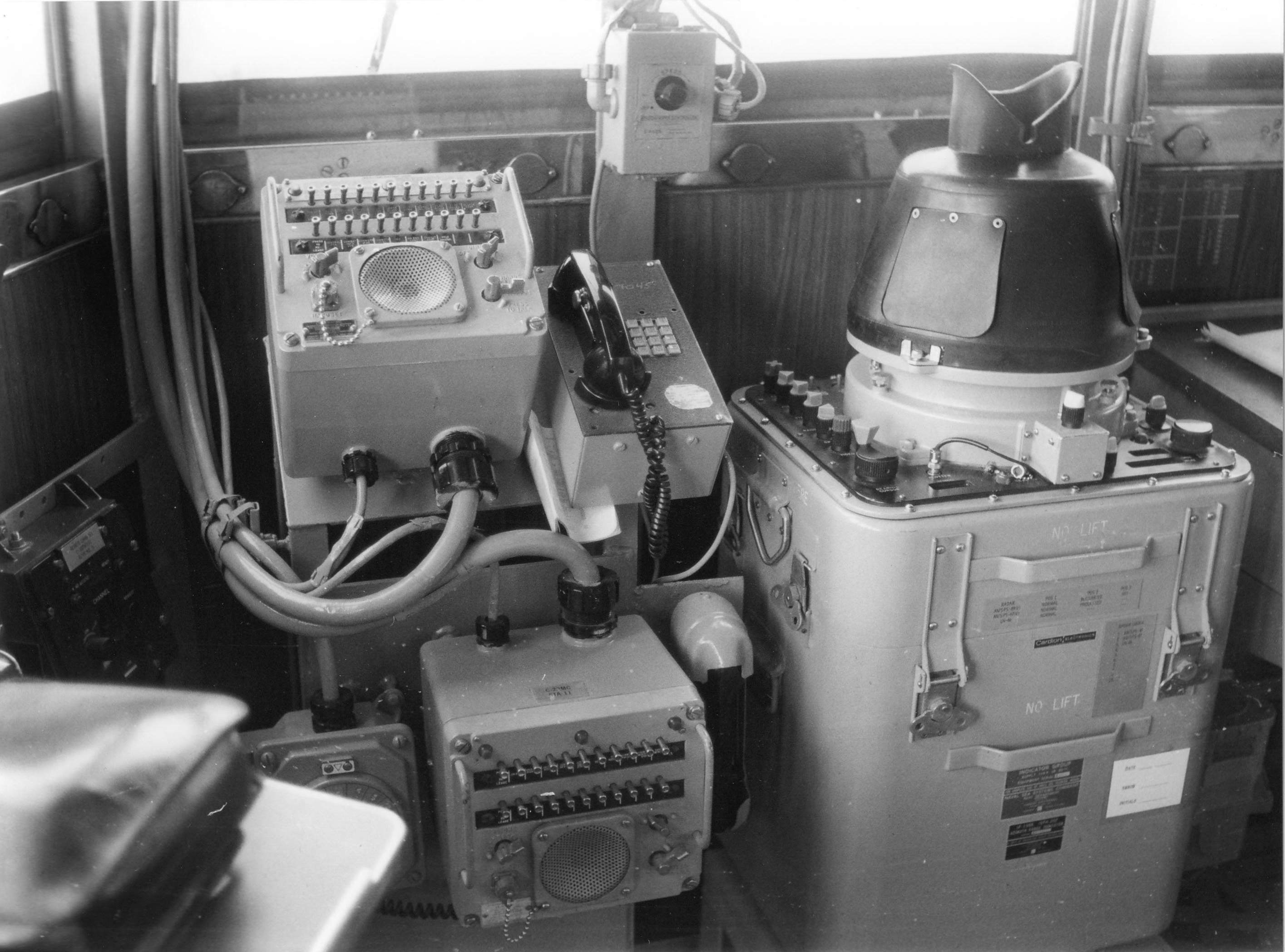
612k | Sound-powered telephone On the left is a view of the Handset sound - powered telephones with a voice pipe in between and radio telephone remote control units that were mounted on Iowa's (BB-61) Navigating Bridge in 1985. A sound-powered telephone system is one in which the only power on the line comes from the spoken voice rather than from an outside source of electricity such as battery or generator. Pictured here is a sailor wearing sound-powered phones while he plots a surface contact. Sound waves from speech strike a thin plate and a needle attached to a diaphragm transmits electrical impulses through the wires to an ear piece where another coil, needle and diaphragm change the current to speech again. When the phones are in good condition and the voice is strong and clear, sufficient current is generated to carry the voice to everyone on the circuit. There is no line noise or line buzz on the phone, except what is allowed to enter by careless handling. Failure of the electrical power system has no effect upon the sound-powered phones although one or more stations can be rendered useless by a shorted or broken line. Telephone circuits Sound-powered telephones were linked together to form circuits. Pictured here are men during an alert aboard South Dakota (BB-57) on 28 March 1945. Note personnel wearing sound - powered headsets tied in to the ship's primary battle telephone circuits. Each circuit had a name and number. Each outlet on a circuit had a number. Primary battle telephone circuits provided means for communication between selected battle stations grouped on established circuits and were designated by standard symbols, each symbol consisting of two (or possibly three) letters- JA to JZ. The number of circuits could vary with the size of the ship. The JA circuit This was the captain’s primary battle circuit. It connected the captain with numerous stations such as forward control, after control, sky control, combat information center and damage control. This was the main fighting circuit of the ship. Over it the captain gave orders to the senior officers and received reports of the progress of the action. The 1JV circuit This was the primary maneuvering and docking circuit and connected the captain with such stations as the forward and after engine rooms, the forecastle, the fantail, the different mooring stations and the after steering station. Over this circuit the captain communicated with everyone who had anything to do with the movement of the ship, direction or speed. In addition to these and the primary circuits there were a certain number of secondary or auxiliary circuits. For example, in addition to the JA circuit, there also was an XJA circuit with outlets in most of the same places as the JA circuit. It served as a standby between stations. These auxiliary circuits were designated by the same letters as the primary circuits, except that they had the letter X in front of the label. By means of switchboards or patch panels, it was possible to tie certain circuits together or cut out parts of a circuit for purposes of isolating damage. For example, during fueling it could be desirable for the chief engineer to have all the stations on one circuit connected with all the stations on another circuit. This could be done by means of a tie switch connecting the two circuits. In case a part of a circuit was shorted, that part of the circuit could be disconnected by means of central switchboards. All these circuits had outlets on the bridge. Some were manned all the time; most of them were manned during general quarters. Other circuits used exclusively in a single department could have no outlets on the bridge or may have had outlets that were used only in special circumstances. In nearly every case, information regarding activities in one part of the ship needed in other parts was sent from station to station by means of sound-powered telephone circuits. This means that the information had to be spoken by an officer, repeated by a telephone talker at the sending station, heard by a talker at the receiving station and then repeated correctly to the officer concerned. The job of a talker was an important one. The talker and his equipment were the nervous system of the ship. If the message was not relayed or incorrectly relayed, the ship could be helpless and her entire crew could be placed in danger by a talker who did not use his voice and his phone well. Two types of sound-powered telephones There were two types of sound-powered telephones- the handset and the headset. The handset telephone talker looked very much like the cradle telephone with a receiver on one end of a bar and a transmitter on the other end. This phone was held in one hand with the receiver over one ear and the transmitter in front of the mouth. In use, this telephone differed from the one at home in that there was a button located on the bar connecting the transmitter and receiver. This button was pushed down each time the talker wished to transmit and only when the telephone was actually in use. If the button was held down at other times, all the noise at the talker’s station would go throughout the circuit and make it difficult for other talkers on the line to understand each other. The handset telephone, when not in use, was held on a bracket on a bulkhead with a lever or spring attachment that held it from being torn loose. When the phone was replaced on the bulkhead, the phone had to be secured or it could fall to the deck and seriously damaged. The handset phone, although very convenient, had certain disadvantages and was used as an auxiliary to the headset phone. The headset type of phone was used more often and by many more men. The headset phone There were two parts to the headset telephone, a pair of earphones mounted in a spring metal clamp that fitted on the talker’s head and a transmitter mounted on a chest piece suspended on a strap around the talker’s neck, so that the mouthpiece was directly in front of the mouth. Pictured here is a talker with headset standing between the Gyro repeater and radar repeater, rudder angle indicators and to his left a chart-log desk. There was a rubber covered wire lead from the phone ending in a heavy metal plug called a jack. This jack fitted into a jack box On the jack box was a small circle of paint that glowed in the dark so that it could be located at night. The circuit and outlet numbers were written on the jack box. Because the headset had several rather delicate parts it had to be put on properly, worn in the correct positions and stowed with care. When putting on the headset telephone, the transmitter had to be held in the left hand and the yoke of the earphones hooked into the space between the chest piece and the transmitter. This insured that the earpieces would not be dropped. Next, the right side of the neck strap was unhooked and fastened around the neck. The earphone yoke was adjusted and the earpieces placed on the head, care had to be taken to have the center of the earpiece directly over the ear. That being done, no portion of the equipment would hand by the leads. Dangling equipment soon destroyed the sureness of electrical contact. The earpieces should never be turned away from the head as this permitted the noises in the vicinity to be picked up and transmitted throughout the circuit. If the station was in or near a boiler or engine room, there could be so much noise that the entire circuit could become useless because one talker’s phones were turned away from his head. The fact that noise was transmitted by the earphones indicates that a single instrument could act either as a transmitter or a receiver. In case of a casualty to the transmitter on a headset phone, you could speak into one earpiece while listening through the other one. In case of a casualty to the earphones on a headset phone, you could hold the transmitter button down and receive as well as send a message with the transmitter. In these ways communications could be maintained. Wearing phones In wearing the phones the following adjustments had to be made and maintained: First, the earpieces had to be adjusted so that the phones were directly over the ears with the head band resting firmly across the top of the head. Second, the transmitter had to be adjusted so that the mouthpiece was directly in front of the mouth. The face of the diaphragm had to be nearly straight up and down. While speaking, the mouth had to be approximately one-half inch from the transmitter. The short lead from the transmitter to the chest piece was a frequent source of trouble. The transmitter was fixed in a gimbal so that it would pivot and for this reason care had to be taken that the transmitter was not twisted around in such a manner that the short wire lead was subject to a sharp bend that would break it. It had to be remembered that one was tied down when wearing the phones. If forgotten, one could walk beyond the length of the cord and break it at the plug. The phone had to be plugged in firmly. If there was a screw collar, it had to be turned on properly. If plugged into the jack box you were ready to listen. In order to transmit a voice the button directly over the mouthpiece had to be pushed and held down when the talker wished to speak. The practice of putting a rubber band or tape around the piece to hold the button down was in general a bad one. Unless authorized to do so, a button should not be fastened down. A button held down resulted in the same effect as having one earpiece outward. Noise would be fed into every set of phones in the circuit. Recordings showed that a telephone circuit could become almost useless. While talking this button had to be pushed down firmly and held all the way down as long as the talker was speaking- otherwise, his messages would be interrupted and would not come through. The phones could never be secured without first having received permission to do so. When securing the phones, the collar was unscrewed and the plug pulled from the jack box. Pulling the lead wire to remove the plug would break the wire. The screw cover on the jack box was replaced. (The screw cover on this box is missing.) Whenever the jack was removed, the cover had to be immediately screwed back in place. Weather, dirt and dust would soon render it inefficient or useless if it was left open. A cover hanging on its chain was a sign that someone was not thinking. If an uncovered box was seen it had to be covered. Storage of phones The phones were hung over the transmitter and the lead wire carefully coiled. If the plug was out of the jack box and on the decks, kinks would be unlikely to form in the lead wire. The transmitter had to be folded and all phone parts secured with the neck strap and stowed in the box provided for them. The box had to be closed properly to exclude salt air or water and prevent contact with the phones. Below decks the phones could be hung on a hook. Phones had to be unplugged no matter what method of securing. Phones that were left plugged would pick up noise and feed it into the circuit. An especially dangerous act was that of placing phones on the deck which would catch the surrounding noise and sent it into the phones with great force. Voice tubes A voice tube requires neither electrical nor sound power bur its effectiveness decreases in direct proportion to the length of the tube and the number of bends it contains. On large ships, communication by voice tube is for short distances only as between open conning stations and the pilothouse. Loudspeaker systems The MC, the battle and general announcing system MC, the battle and general announcing system is a multi-channel (MC) circuit over which word could be passed to almost every space in the ship. The general alarm system was tied into it as well. Transmitters were located at the bridge, quarterdeck and central station and additional transmitters could be at other points. The OOD was in charge of the MC and no call could pass unless authorized by him, the executive officer or the captain. The MC was equipped with cutout switches to exclude certain spaces. The most common use of the MC was in carrying out the ship’s routine. Also associated with the 1MC communication system were the ship’s alarms. The general alarm was a distinctive sound signal of a pulsating ringing tone which was used to call all hands to their general quarter stations. For exercise general quarters the word normally passed was: ”this is a drill” before the alarm was sounded. The chemical alarm is a distinctive 1,000-cycle steady tone used only for warning of impending gas attack. Ships also have a special howler as part of the general announcing system that is sounded when a collision is imminent. Bells The ship’s bell is used in conjunction with the fog gong for sounding fog signals when at anchor. The bell is rung rapidly for not less than five seconds and when a ship’s boats were in use the ringing was followed by the number of strokes necessary to indicate the last digit of the ship’s hull number. Another use of the bell was the traditional one of keeping time- the bell was sounded when prescribed by the senior officer on the hour and the half hour from reveille until taps. The ship’s bell was also used to indicate the arrival or departure of visiting senior officers, embarked unit commanders and the commanding officer. Boat gongs were sounded in port to indicate the prospective departure of a liberty boat. MC's Some MC circuits provided a two-way communication and in this they differed from the PA systems. The 21MC, familiarly known as squawk boxes had units with a number of selector switches. In order to talk to one or more stations, it was only necessary to throw the proper switches and operate the press-to-talk button. The chief disadvantage of the intercom was that it raised the noise level in any space in which it was located. For this reason, it was seldom used when sound-powered telephones were manned. The intercom systems were normally used by officers and were limited to emergency business if paralleled by sound-powered telephones. The standard sound-powered phone talker’s procedure was used on the MC circuits. |
Text courtesy of Pieter Bakels. All the photographs taken aboard the Iowa (BB-61) are courtesy of Stef Willems & Pieter Bakels. Remaining photos are USN and submitted by Pieter Bakels. |
|
| Back To US Battleship Construction Index | Back To The Main Photo Index | Back To The Battleship Photo Index Page |
This page is created by Pieter Bakels and Michael Mohl & maintained by Michael Mohl
All Pages © 1996 - 2025, by Paul R. Yarnall NavSource Naval History. All Rights Reserved.