| Click On Image For Full Size Image |
Size | Image Description | Contributed By And/Or Copyright |
|
|---|---|---|---|---|
 |
28.2m | The schooner HMS Dominica is intercepted by the American privateer schooner Decatur of Charleston, SC. on 5 August 1812. PDF article entitled "Operating Instructions for 5-Inch 38 Caliber, Gun Crews / February 1943" United States Fleet Headquarters of the Commander in Chief. |
Photo & article courtesy of Pieter Bakels. | |
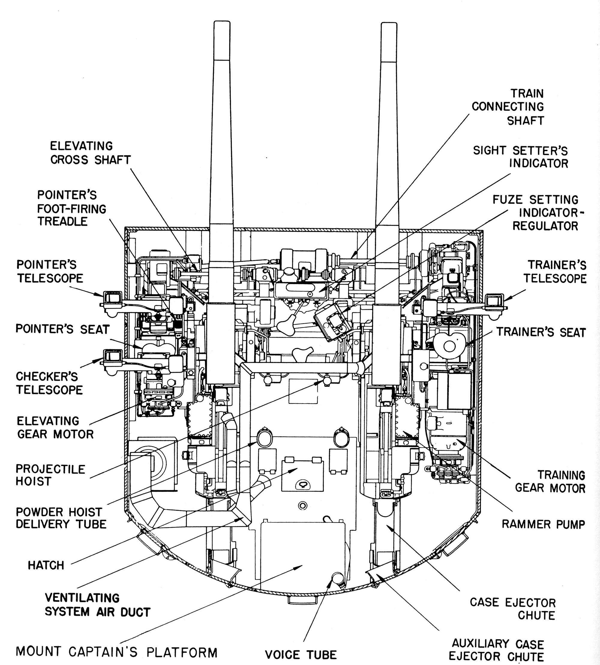
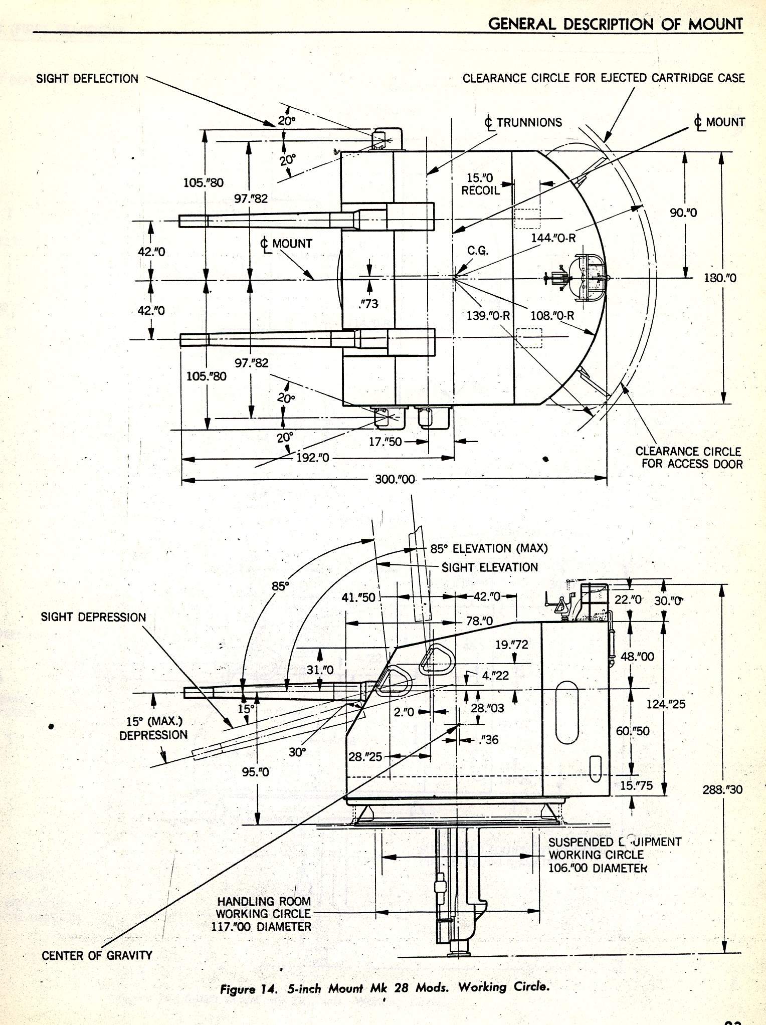
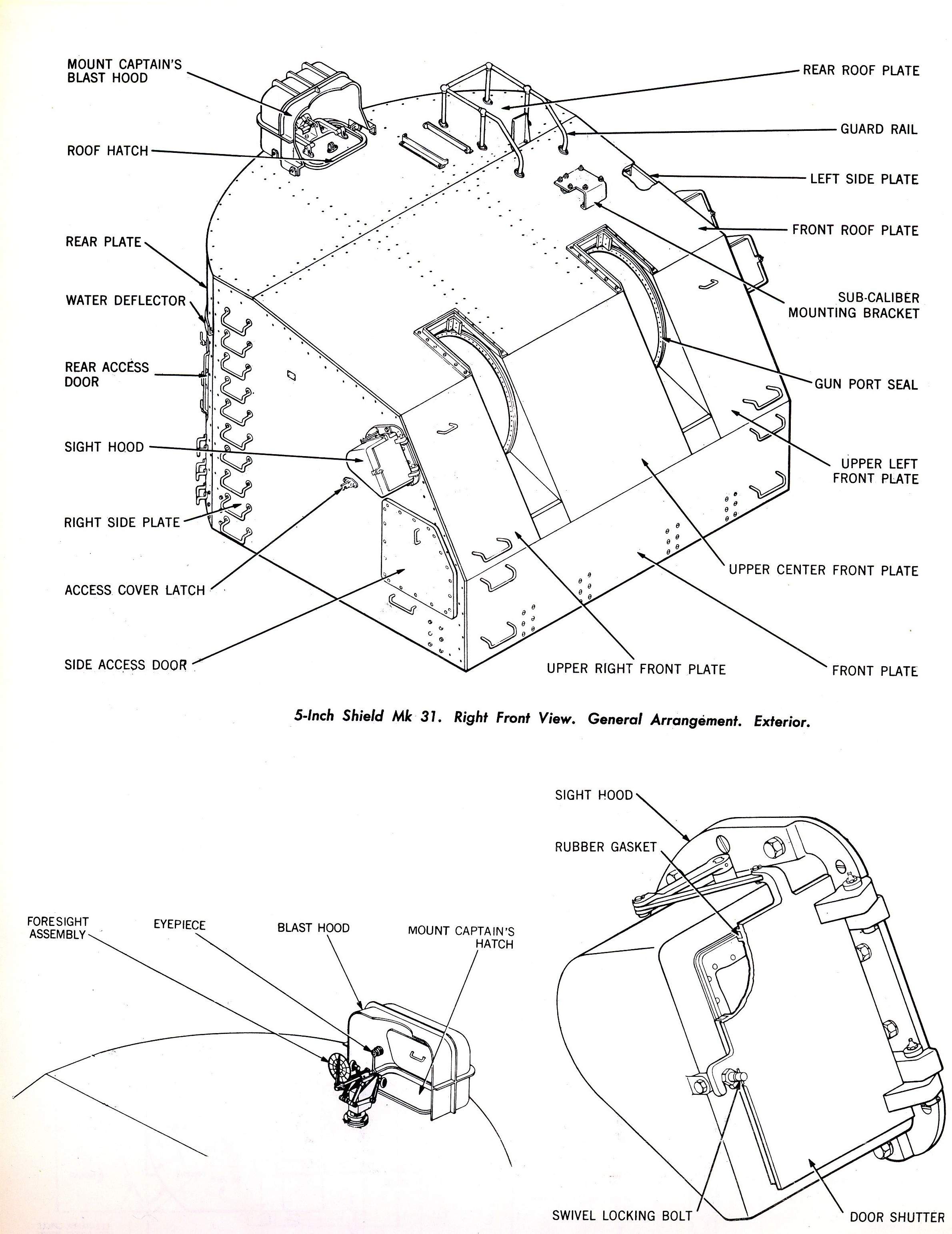
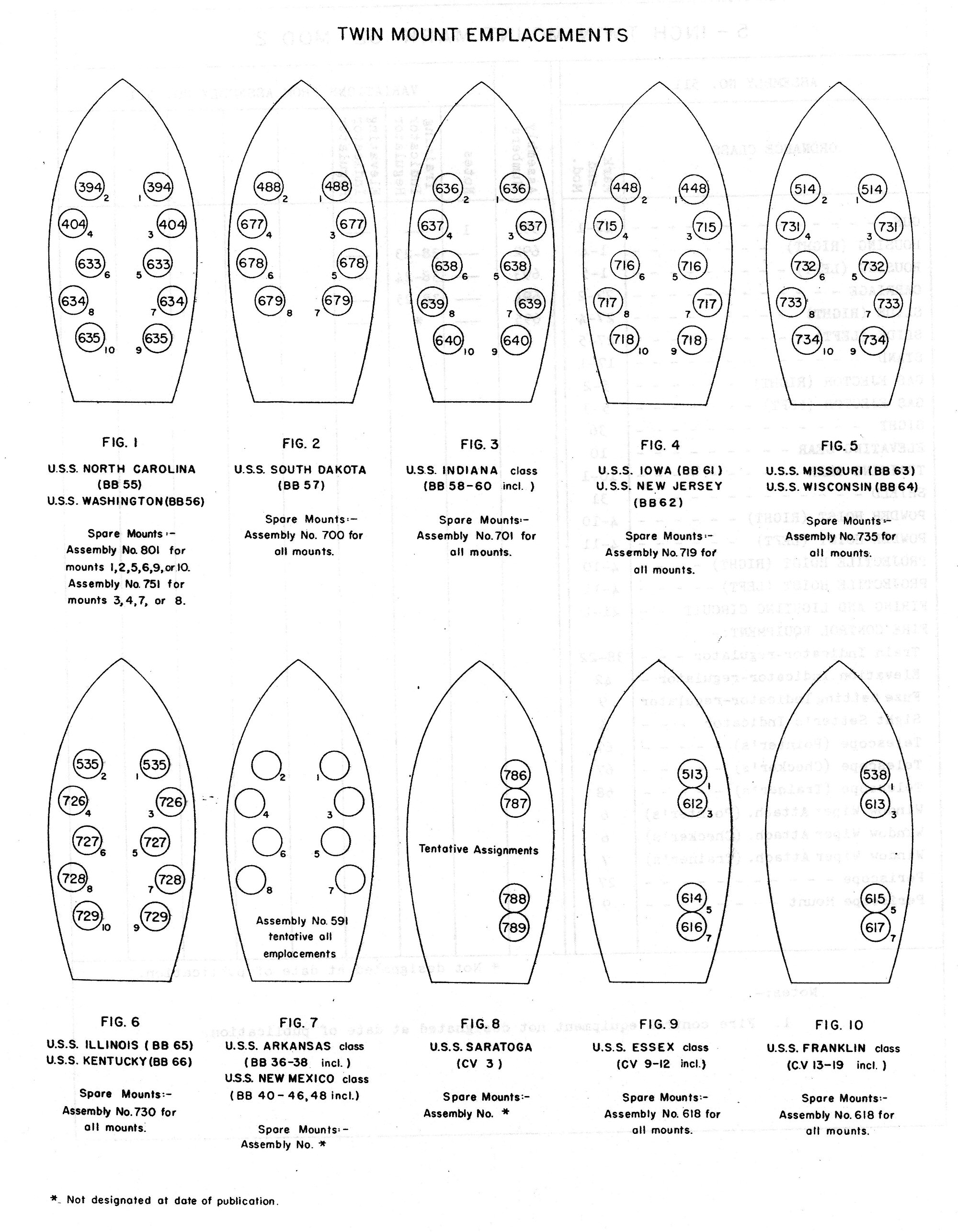
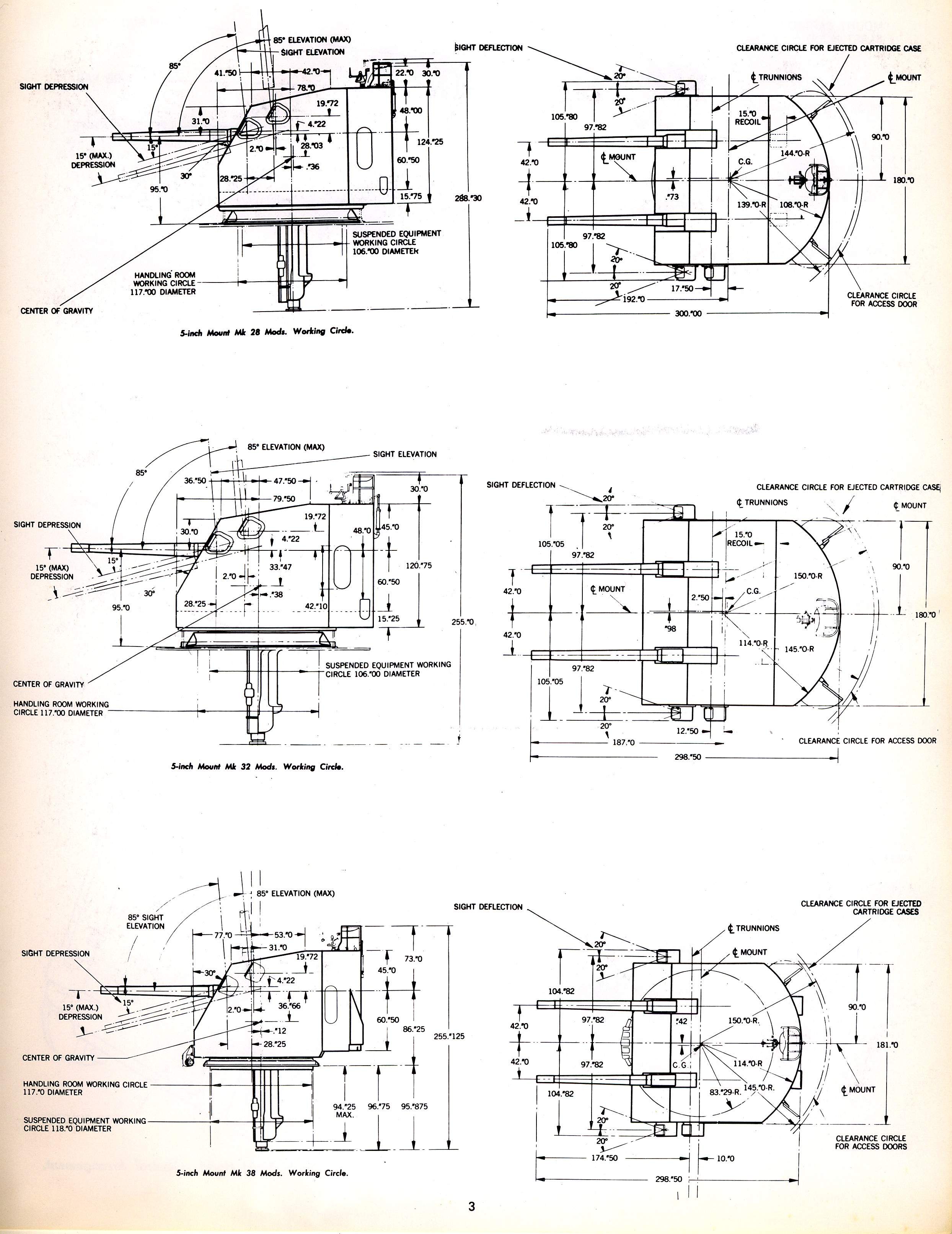
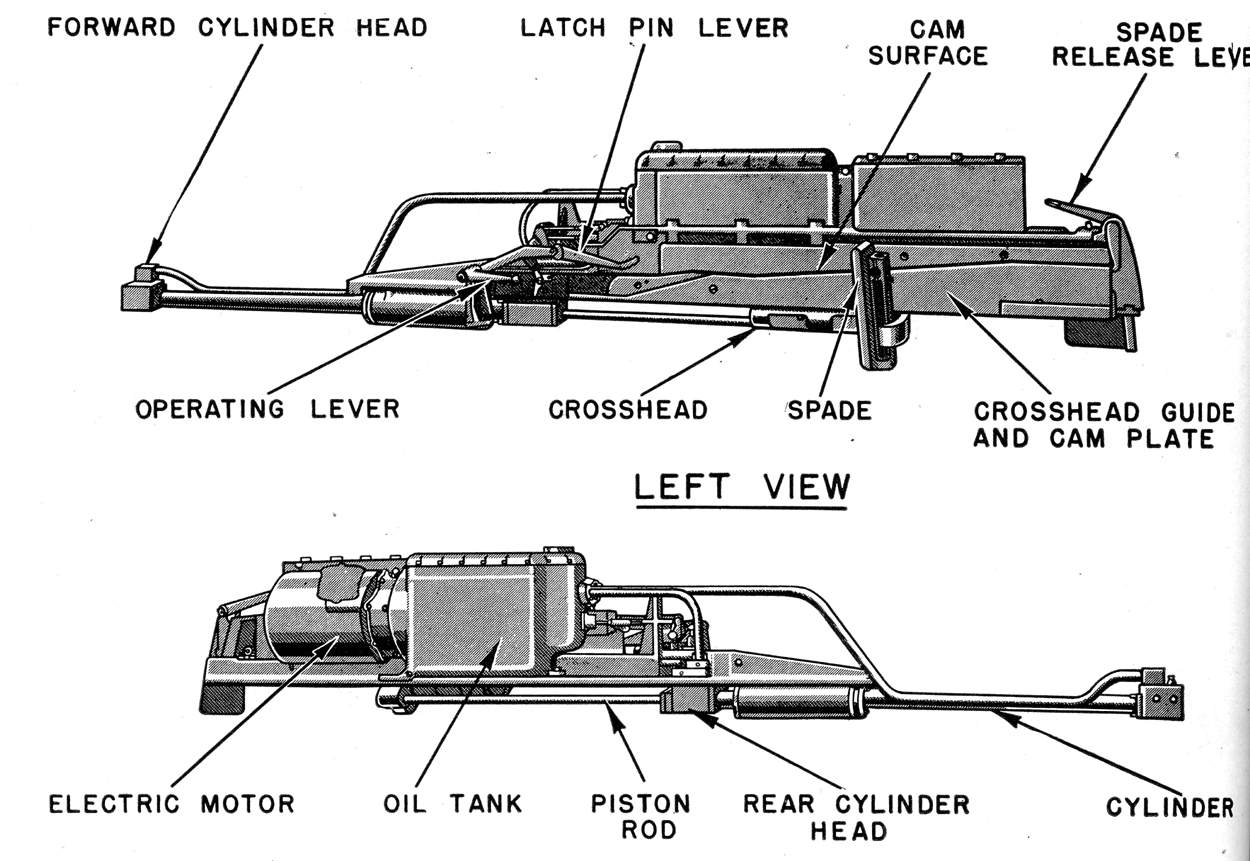
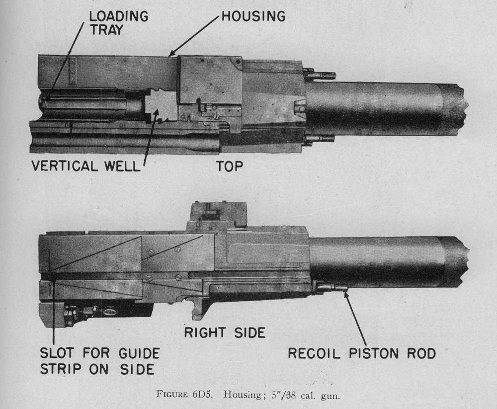
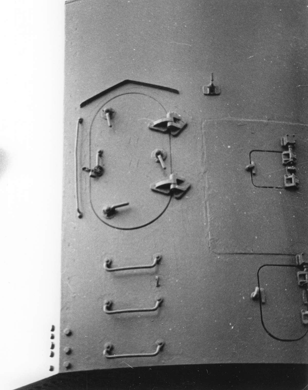
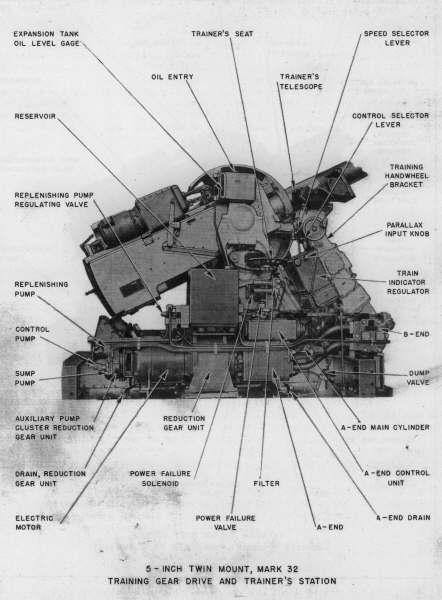
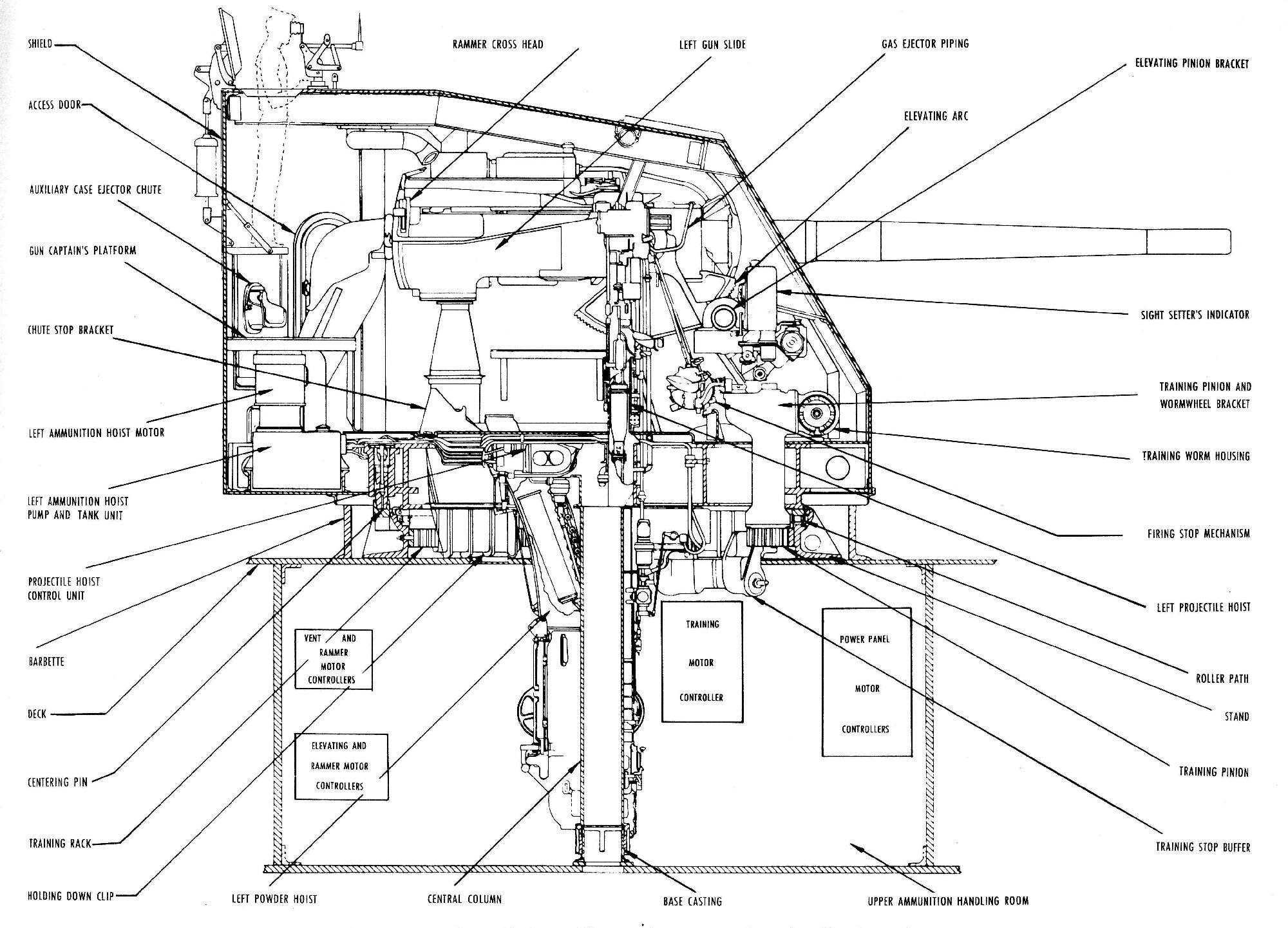
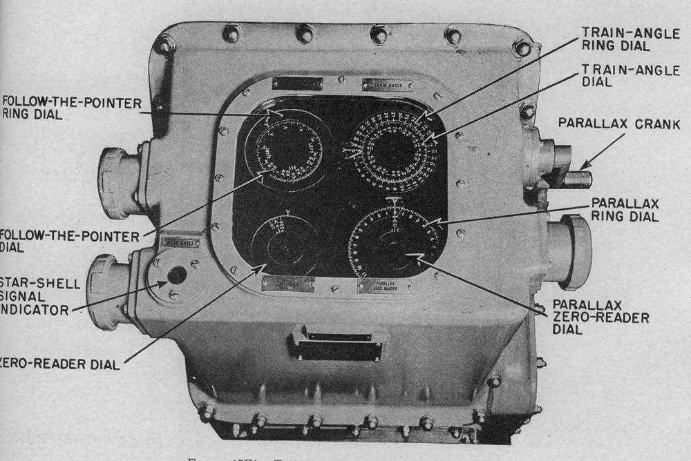
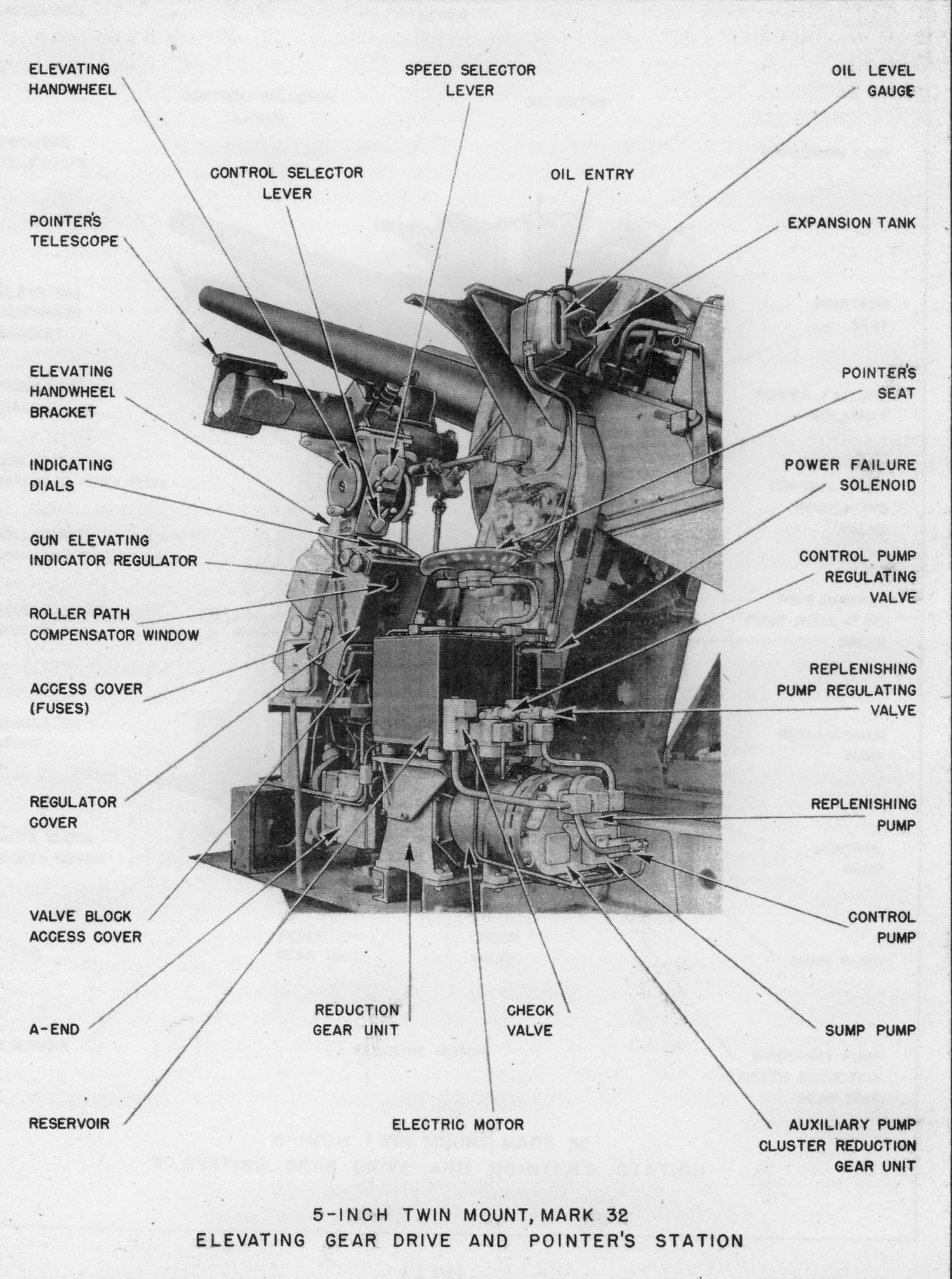
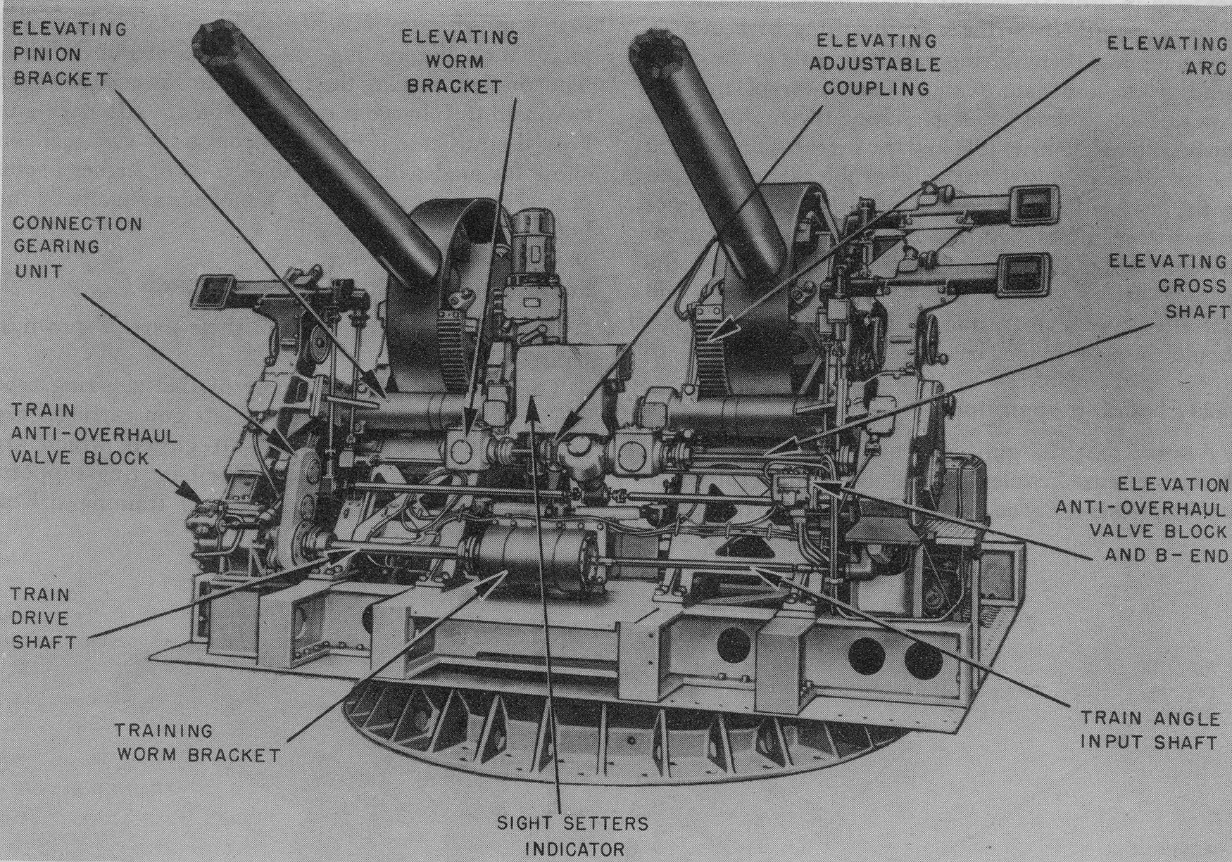
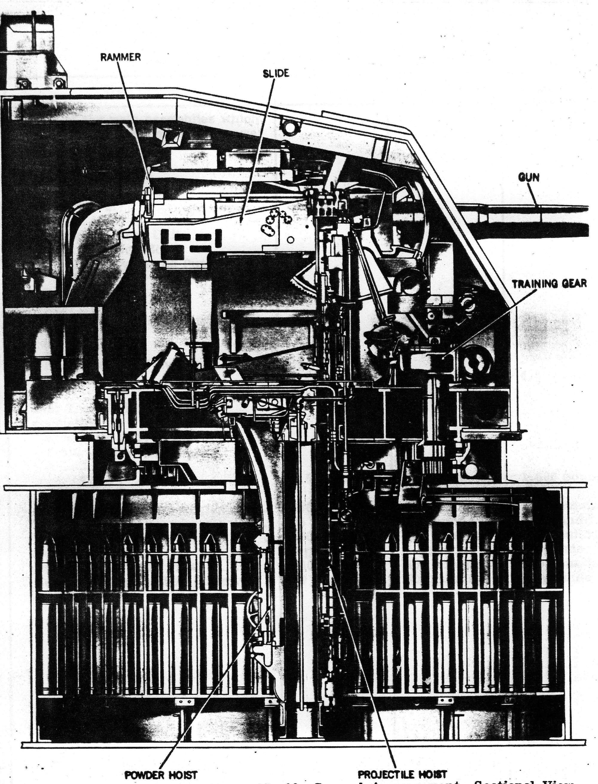
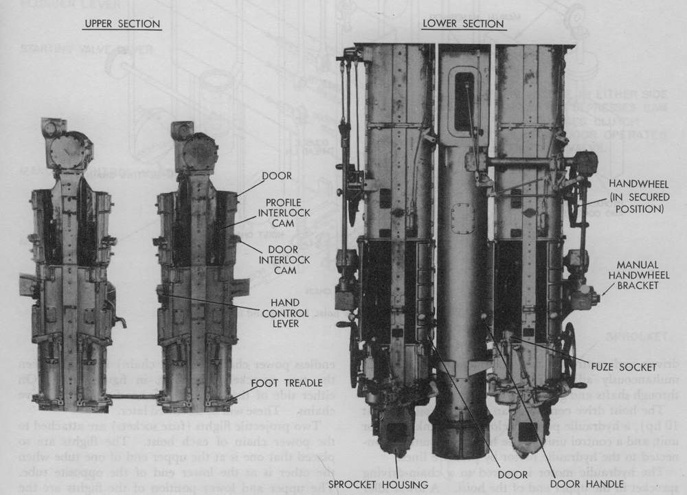
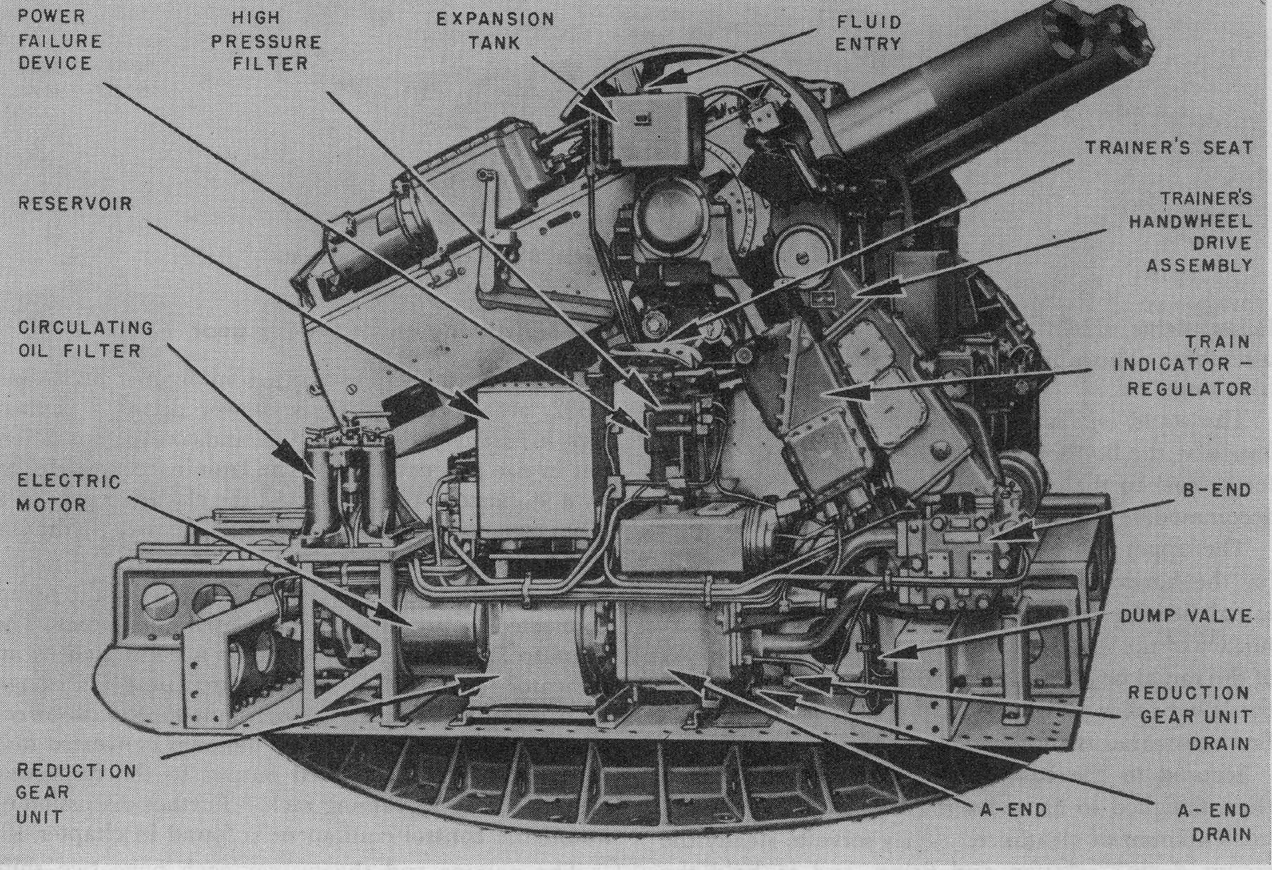
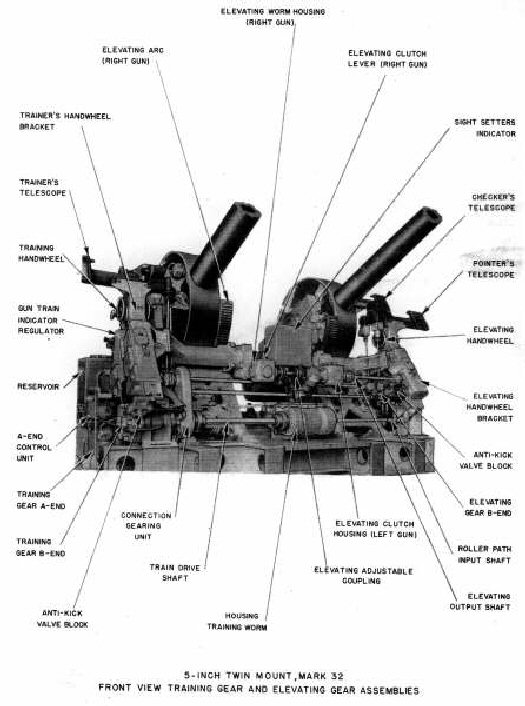
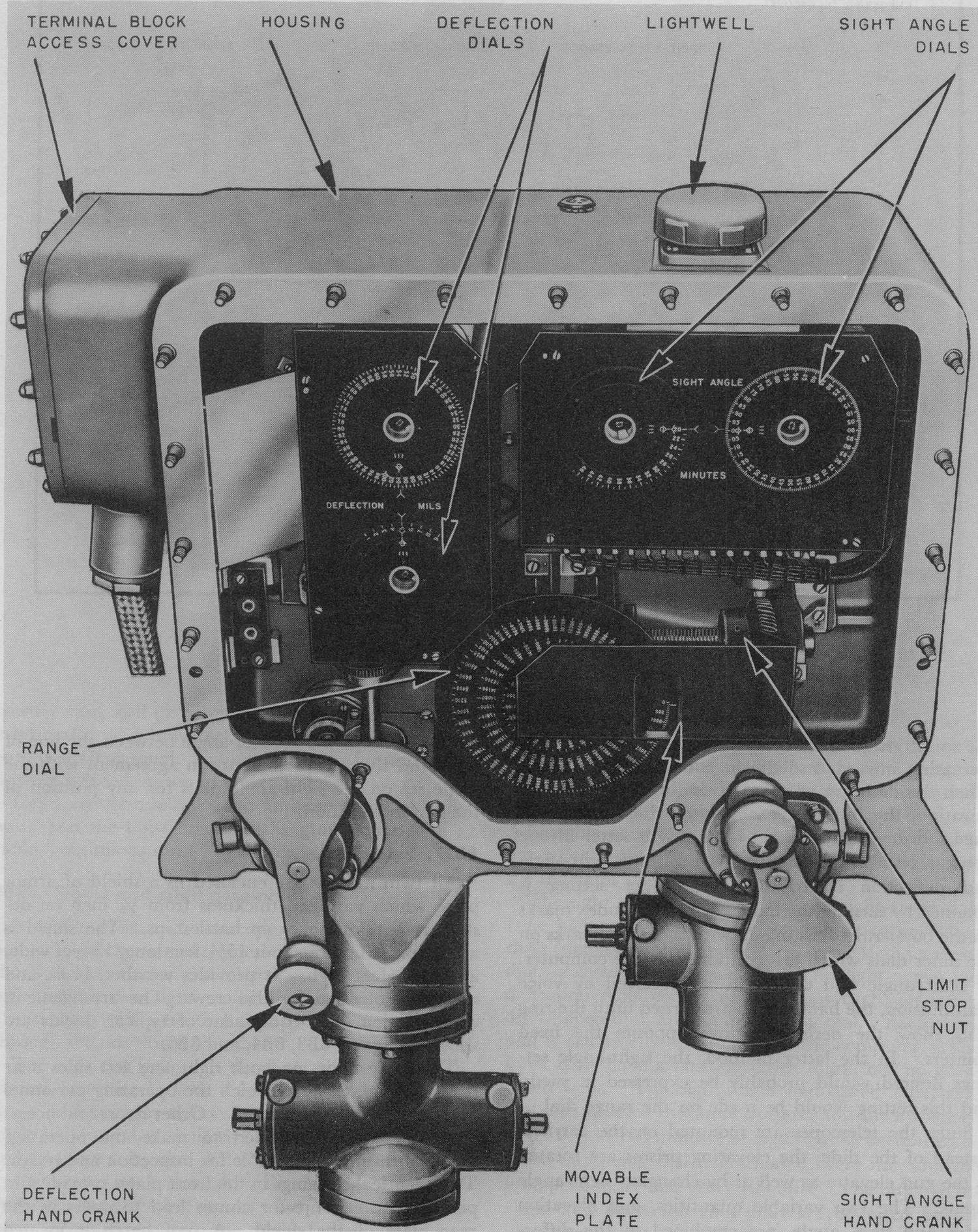
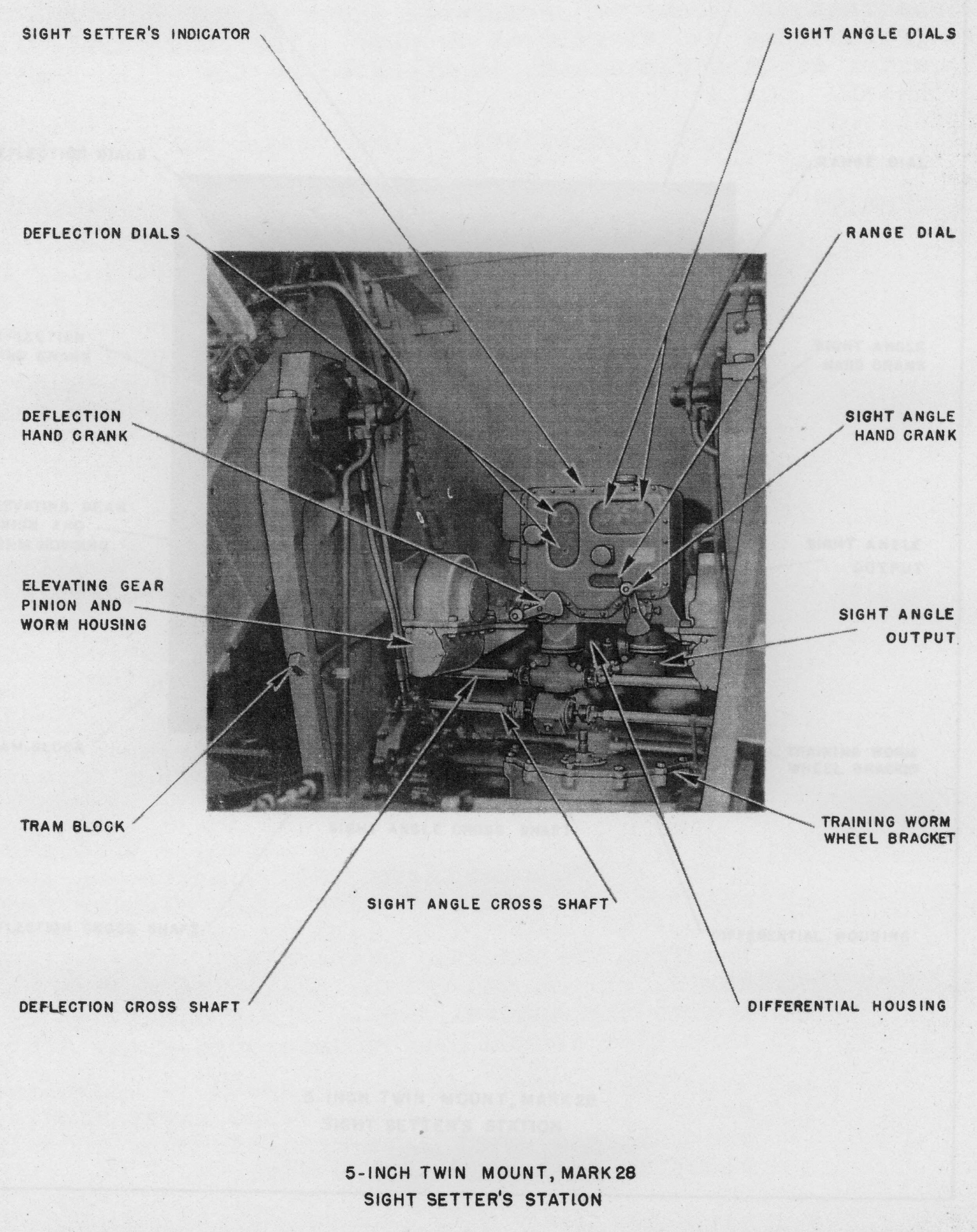
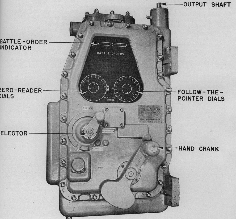
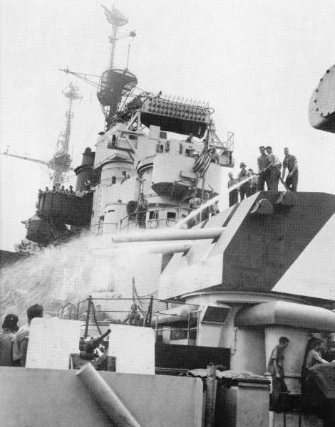
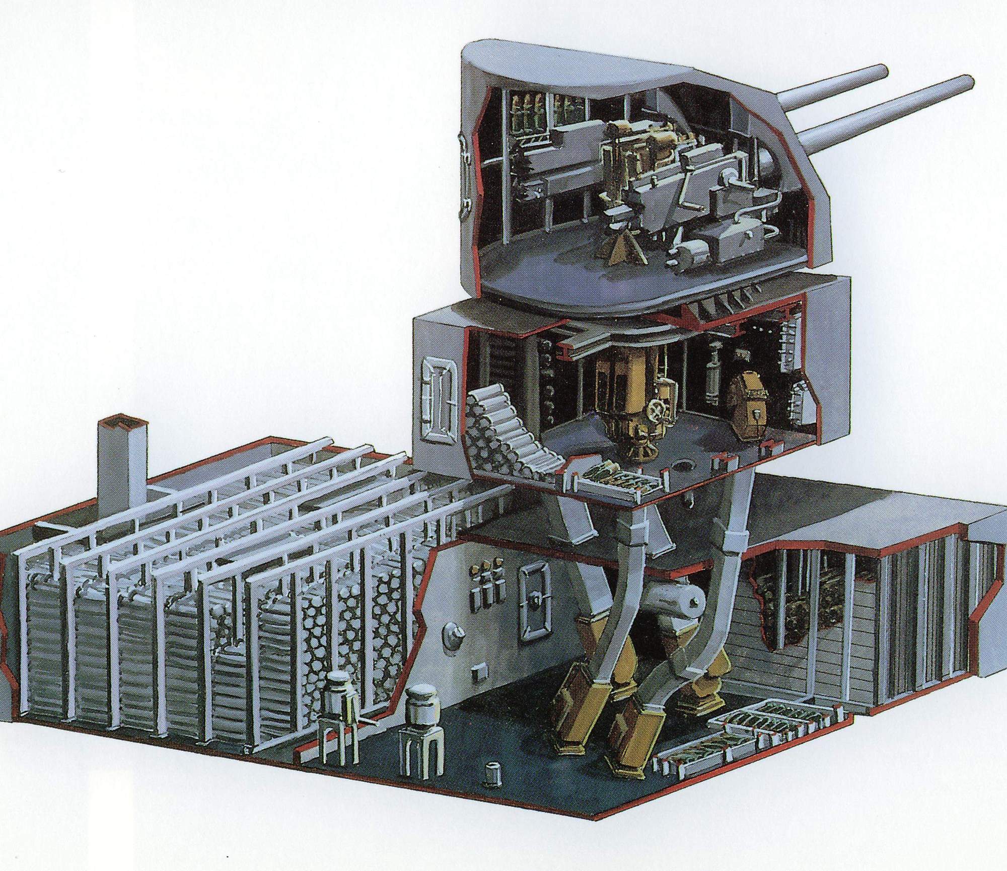 | 1.2m | Battery Introduction Plan view of 5-Inch, 38-caliber gun chambers of turret and magazines on a battleship showing projectile and powder stowage. The Secondary battery (“five inch battery”) of South Dakota (BB-57) consisted of eight enclosed twin mounts, four on each side, with associated directors, computers and ammunition supply. The guns were 5-Inch, 38-caliber and fired semi-fixed ammunition. The mounts were dual-purpose (for use against air or surface target) and could be employed for shore bombardment, star shell illumination and smoke screening. Radar control permitted accurate pointing by day or night. The battery was designed to fire with an initial velocity of 2600 f.s. and a horizontal range band of 2000 to 18,000 yards and to an altitude of 37,000 feet (at maximum gun elevation). The four-director control system permitted simultaneous firing on two targets per side, except on bearings 30 degrees either side of ahead or astern. The rate of fire per gun was 12 to 18 rounds per minute, depending on the type of fire and gun elevation. The above illustrate the importance and versatility of the Secondary Battery and for these reasons, four to eight mounts were manned day and night underway and two mounts were manned day and night in port. Arrangement The battery was divided into four groups, each consisting of a director, computer and two mounts with their ammunition spaces. Group One included director and computer #1 controlling mounts #1 and #3 on the starboard side forward and normally firing in Sector I (0 - 90 degrees relative). Similarly, Group Two included director and computer #2 controlling mounts #2 and #4 on the port side forward, firing in Sector II (270-360 degrees relative). Group Three included director and computer #3 controlling mounts #5 and #7 on the starboard side aft, firing in Sector III (90-180 degrees relative). Group Four included director and computer #4 controlling mounts #6 and #8 on the port side aft, firing in Sector IV (180-270 degrees relative). Switching arrangements in the plotting room permitted any director to control any mount through any computer and mounts could fire on any bearing on either side to which they could train. Each of the two mounts in a group was located above its own Upper Handling Room, from which ready ammunition was supplied to the guns. For each group there was provided a combination Lower handling Room and Magazine on the third deck, from which replacement ammunition was hoisted to the Upper handling Room. Equipment and Ammunition The description of units given here is a very brief outline of the details in Ordnance Publication 805. The information in this book on casualties and operation of breech mechanism, firing, lock, rammer hydraulic units and hoist controls was required reading for gunner’s mates and division officers. The 5”/38 Twin Mount, Mark 28 Each mount was a “base ring” type, shield-enclosed emplacement for two 5”/38 dual-purpose guns. The guns were rapid firing, tray loading pieces with semi-automatic breech action and power rammers which permitted loading at any angle of elevation. The mount had power driven train, elevation and ammunition hoisting with alternate manual operation. The mount was supported and rotated on a stand which was a ring-shaped structure bolted to the deck around the circular opening above the upper handling room. The stand included a roller path, annular training rack and train limit stops. Secured to the deck outside the stand is a circular coaming or barbette with a water-seal on the upper edge to protect the roller path. All rotating parts of the mount were attached to the mount carriage, which was a rectangular platform supported on the stand by the roller path bearings and held in place by holding-down clips. The mount carriage supported the guns in two vertical sets of gun carriages and trunnion bearings. Attached to the bottom of the carriage and rotating with it was a center column which extended downwards to the upper handling room deck and carried the ammunition hoists, air line and electric cables. The slides provided movement in elevation for the guns by means of trunnion journals which rotated on a horizontal axis through the trunnion bearings of the gun carriages. All parts attached to the slide, including gun and housing, rammer elevating gear segment and gun port shield, pivoted in elevation with the slide. The housing was secured to the breech of the gun and supported the gun in the slide where it controlled the recoil and counter-recoil. It contained recoil and counter-recoil cylinders, breech mechanism and firing lock and gas ejector. All parts attached to it moved in recoil. The guns were mono-bloc, radially expanded pieces with rifled chromium plated bores. They were supported in the slide by the housing and by a cylindrical bearing at the front of the slide. A 2” armor plate shield surrounds the assembly and was secured to the edges of the mount carriage. It protected mount personnel from weather and splinter damage. It included access doors, mount captain’s hatch, gun ports, sight hoods, hot case chutes and openings and a forced ventilation system. The training gear , located on the right side of the carriage was a 40 H.P. electric drive, hydraulic transmission operating a worm, worm wheel and train pinion which meshed with the training rack on the stand. An indicator-regulator and handwheel assembly controlled train locally or from the director. The elevating gear, located on the left side of the carriage, was a 7 1/2 H.P. drive similar in design and control to the training gear, except that the output to the elevating worm, worm wheel and pinion at each gun was taken from a cross shaft which could be unclutched from either gun. Hoists There were four separate, power-driven ammunition hoists extending from the upper handling room to the mount, one projectile and one powder hoist for each gun. They were mounted around the carriage center column and rotated with it. The powder and projectile hoist of each gun had a common electric motor drive and individual hydraulic transmission and control. Each projectile hoist was a double tube with reciprocating chain hoist which lifted projectiles alternately in each tube and set the time fuzes while hoisting. The powder hoists were single tubes with endless chain drive. The pointer and checker’s sights on the left side of the assembly and the trainer’s sight on the right side were identical stationary telescopic sights in which gun elevation (and sight angle and deflection from a manually operated indicator) was introduced through shafting to the optical system of the telescopes. Pictured here is the Sight setter's indicator and Sight Setter's Station. A periscope in the shield roof provided target observation and spotting facilities for the mount captain. Upper Handling Room This space beneath the mount was a box-shaped, 2” armored compartment, containing ready ammunition and hoist facilities as a “relay station” in the ammunition train from magazines to guns. Access was via a deck hatch in the mount or armored door to adjacent spaces. Equipment installed included: lower end of upper hoists, upper end of lower hoists, bins and racks for 90 rounds of ready projectiles and powder, deck scuttles for disposing of empty powder tanks, electric control panels for all mount motors and a sprinkling station. Lower Handling Room and Magazines Service ammunition was stowed in insulated compartments on the third deck within the armor citadel. Access was via water-tight doors from the engineers’ passageway. The compartments were provided with sprinkling systems with local and remote control. Powder magazines only were air-conditioned. The lower handling rooms contained stowage bins for 2000 projectiles, hoists for projectiles and powder and door and scuttle access to the powder magazines. The powder magazine was a separate compartment adjacent to each lower handling room and contained stowage bins for 2000 powder cartridges in tanks. For groups #2 and #3 an individual handling room and magazine served each mount. In groups #1 and #4 a single large handling room and magazine served both mounts. In either case, one projectile and one powder hoist per mount was installed. All lower hoists were identical, except in length and were Northern Pump Co., electro-hydraulic, endless chain type, enclosed in square armored tubes between upper and lower handling rooms. Each unit could hoist or lower projectiles or powder tanks and was provided with interlocking controls at each end to cause operation through one cycle only whenever a piece of ammunition was put in or removed at either end. Ammunition The stowage and supply of ammunition was subject to change and was covered in battery memorandums in director files. The 5”/38 load was in two pieces, a 28 pound powder cartridge (charge) and a 54 pound projectile. The cartridge was a brass case filled with 14.75 pounds of smokeless powder and closed at one end with a cork plug and at the other end with an integral rimmed base fitted with a combination ignition primer. The primer was protected by a cap which was removed when the cartridge was loaded in the gun tray. The whole was stowed in an airtight tank for protection. There were two types of cartridges, smokeless for day action and flashless for night action, the latter stowed in tanks marked with a red spot. Four typed of projectiles were provided for various purposes: 1- A.A.Common with Mark 18 fuzes. This was the basic, multi-purpose round for anti-aircraft or surface firing or in shore bombarding. The nose fuse could be set to detonate the projectile by clock work in a pre-set interval after firing or the base fuse could detonate the projectile on contact with surface or shore target. All rounds contained a red or white tracer. 2- A.A.Common with Mark 32 fuze. This type was for anti-aircraft. It required no pre-setting of the nose fuse and had no base fuse or tracer. 3- Common (“surface”) projectiles could penetrate 2”armor and were used against ship or shore targets. They had a solid nose, base fuze and tracer. 4- Illuminating projectiles starshell contained a parachute-suspended flare which was ejected in flight when the Mark 18 nose fuse functioned at the pre-set time. To ensure that it did so was the job of the Elevating Indicator Regulator. There was no base fuse or tracer. Other type projectiles sometimes carried included: 1- WP projectiles containing white phosphorus for smoke screen or incendiary use and fitted with time fuze. 2- B L & T projectiles for surface target practice, similar to common but without explosive filler or base fuse. Dummy cartridges, tanks and projectiles were provided for drill use. Pictured here is a cross section of a Radio Proximity Faze (VT), essentially a rugged sending-and-receiving station. Ammunition Doctrine for 5” Battery The basic principal of the Doctrine was maintenance of Mark 18 supply in the upper handling room. One had to remember that the Mark 32 could only be used against air targets; Common could only be used against surface targets but Mark 18 could be used for bombardment or on any target with fair results. Ready ammunition for air target (75% Mark 32, 25 % mark 18) and for light surface target (100% Common). Three minutes notice were given for heavy surface targets (100% Common). Thirty minutes notice for shore bombardment (Mark 32 secured). Upper Handling Room Stowage Powder bins: 2/3 flashless, 1/3 smokeless. #1 projectile bin-all mounts: 40 rounds mark 18. #2 projectile bin-all mounts: 40 rounds Mark 32. Bulkhead racks-high mounts: 30 rounds star-shells. On deck- no projectiles. Supply from Lower handling Room Air target: high mounts: Mark 32, low mounts Mark 18. Light surface target: all mounts, Mark 18. Heavy surface target: all mounts, Common. Powder: all mounts: flashless at night and smokeless in day. No projectiles would normally be stowed on the upper handling room deck, to allow more room for the crew and to provide space to set aside “wrong” projectiles cleared from lower hoists. During action, the lower hoist could not be reversed or run with empty flights. When target types changed and the wrong projectiles were in the hoists, they were cleared by loading the correct projectiles below and the wrong projectiles were set aside above. During definite lulls, Air Defense would give permission to reverse the hoists to return the projectiles to normal set-up. All fuzesetters (pictured here is a fuze setter indicator) would be in automatic and fuze knobs out in order to prevent confusion of fuzesetter. “Reload cartridges” with short corks were necessary when clearing a gun and would be kept at hand. Directors would consider all surface targets “light” (destroyer, submarine, patrol boat, merchantman, etc.) and used Mark 18 with safe fuse setting. When definitely identified visually or by CIC as “heavy” (CV, BB, CA, CL), Mark 18 was used until shift to Common could be made. Misfire Procedure The following steps would be taken in action whenever a loaded gun failed to fire after “commence firing” had been received for rapid fire (or after a buzzer had sounded for surface fire): 1- It had to be checked if the mount was in a firing cut-out position and if it had returned to battery. 2- It was reported to the director that “mount ….was in the stops” or “mount…..misfired”. 3- The pointer kicked his foot pedal once and shifted circuit to ”battery”. 4- The bottom of the breech block was tapped with a maul even though it could appear completely closed (failure of breech to close by as little as 1/8”would cause misfire). If the breech failed to close after one tap, it was not hammered shut but the cartridge extracted and reloaded. 5- After tapping the breech, the foot pedal was recocked and kicked once more. 6- It had to be checked again if the mount was in the firing cut-out position. 7- The cartridge was extracted with spade down and reloaded. 8- When the extraction was difficult or impossible (as when the gun was not in battery) and if the gun was too hot to keep the hand on (usually twenty or more rounds fired in rapid fire), unnecessary personnel was cleared out and the muzzle hosed down and the slide cylinder hosed outside of the mount. The director was notified of this. When a misfire occurred during target practice, step one to six were followed and instructions requested from the director officer. A hot gun was unlikely during a target practice. The above procedure was intended to correct first the most probable cause of misfire and to restore the rate of fire as soon as possible without endangering the crew. Unless repeated electrical misfires indicated a fault in the primary firing circuit, the switch was not left on “battery”. The “battery” method bypassed the director key and prevented proper director control of firing. A faulty cartridge was never forcibly extracted by heavy pressure on the breech operating handle but by tension, used on the extracting tool at the same time as the handle was moved. Ammunition Handling 13 page PDF article from the Massachusetts (BB-59) Battle Bill. |
Text courtesy of Operation & Description of Ordnance Installation aboard USS South Dakota" (BB-57), August 1944, complied and edited by Pieter Bakels. USN photo submitted by Pieter Bakels. |
|
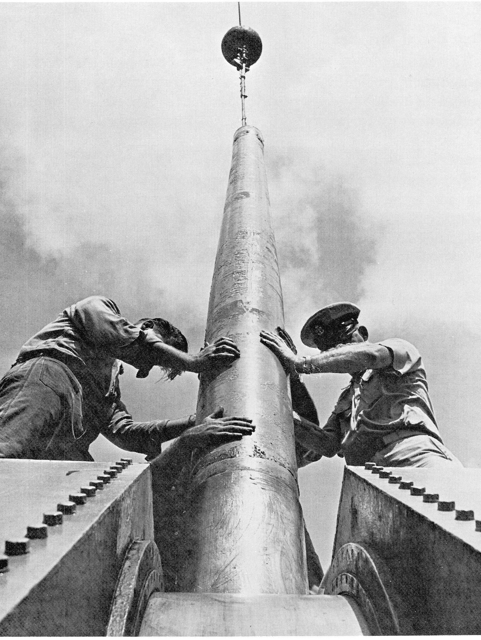 |
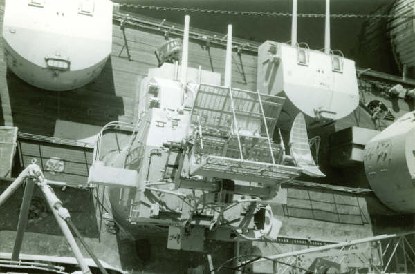
1.00k | A new barrel is fitted to a 5-Inch, 38-caliber gun mount. | USN photo courtesy of Pieter Bakels. | |
 |
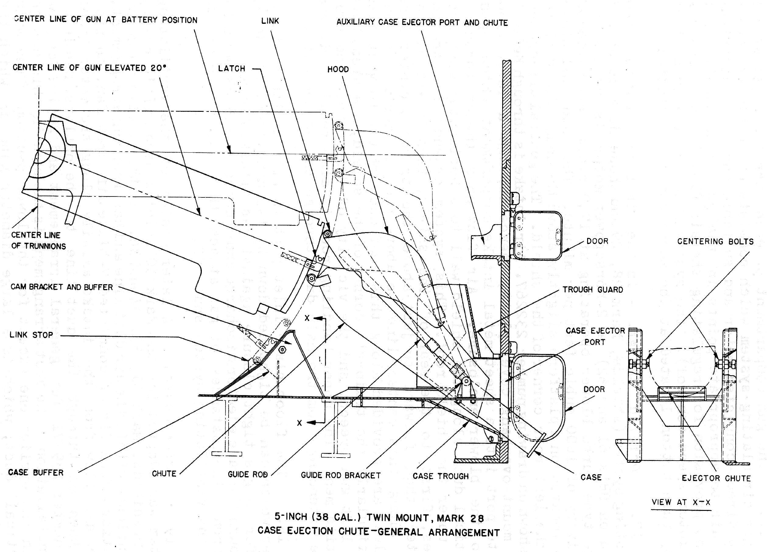
2.50k | General arrangement of a 5-Inch,38-cal. twin mount showing ammunition stowage. Also shown here are several high resolution images showing: 5-Inch Twin Gun Mount Mk.28, G.A.,Sectional View. (NavOrd OP 808, 3rd.Rev.) Gun Assembly, Installed Arrangement & Structural Support of Gun and Housing in Slide. (NavOrd OP 805, 3rd.Rev) Projectile & Powder Hoist MK.4. |
USN photo courtesy of Pieter Bakels. | |
 |
109.k | 158 PDF images of 5 inch. | Photo courtesy of Pieter Bakels. | |
 |
104.k | 708 page PDF images of 5 inch. | PDF courtesy of Pieter Bakels. | |
| Back To US Battleship Construction Index | Back To The Main Photo Index | Back To The Battleship Photo Index Page |
This page is created by Pieter Bakels and Michael Mohl & maintained by Michael Mohl
All Pages © 1996 - 2025, by Paul R. Yarnall NavSource Naval History. All Rights Reserved.