Please Report Any Broken Links Or Trouble You Might Come Across To The Webmaster.
Please Take A Moment To Let Us Know So That We Can Correct Any Problems And Make Your Visit As Enjoyable And As Informative As Possible.
| Click On Image For Full Size Image | Size | Image Description | Contributed By And/Or Copyright |
|
|---|---|---|---|---|
| 1939 - June 1942 / Keel Laying - Commissioning |
||||
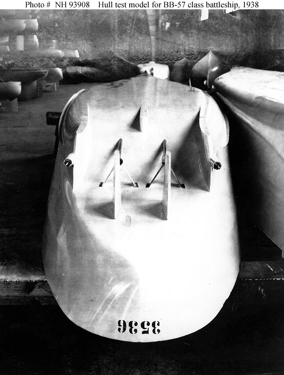 |
76k | Hull test model for the South Dakota class (BB-57 - 60) battleships. Hull model number 3536, photographed at the Experimental Model Basin, Washington Navy Yard, Washington, D.C., in 1938. Note the widely spaced skegs, supporting the outboard propeller shafts, that were a unique feature of this battleship class. Copied from the Bureau of Ships monograph "United States Battleship Designs for World War II", dated 1 June 1946. | Naval History and Heritage Command # NH 93908, from the collections of the Naval Historical Center. | |
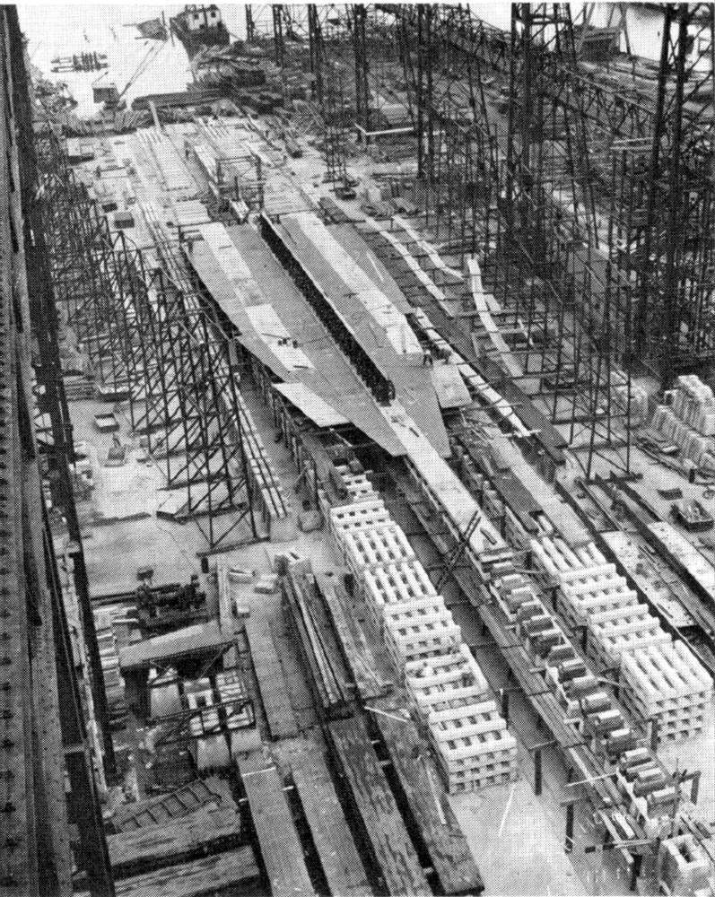 | 226k | August, 1939 view of the construction, less than a month after the July 20th keel laying. The Massachusetts (BB-59) is basically a few outer bottom plates and part of the keel. The support blocks divide aft to eventually support the twin skegs of the tunnel stern. | Official USN photo courtesy of Mike Green / Leeward Publications "SHIP'S DATA". | |
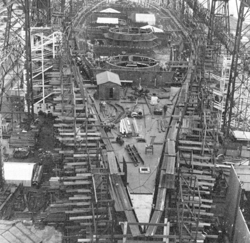
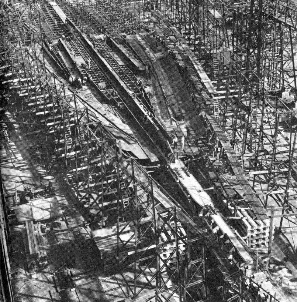 | 264k | 6 October 1939 view of construction looking aft from the bow. The rise over what would become the tunnel stern is evident in the far end of the photo. | Official USN photo courtesy of Mike Green / Leeward Publications "SHIP'S DATA". | |
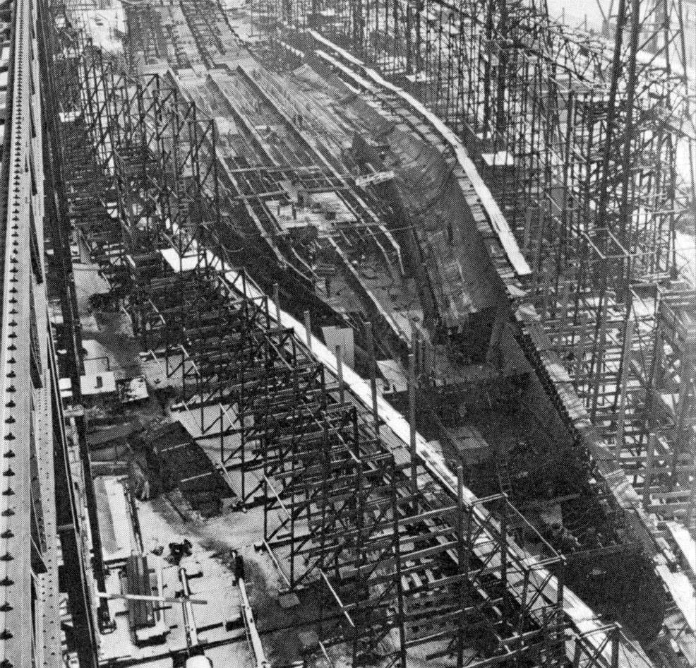 | 256k | 4 January 1940 view of construction looking aft from the bow area. In the background work is beginning on the two skegs which are widely separated in this class. | Official USN photo courtesy of Mike Green / Leeward Publications "SHIP'S DATA". | |
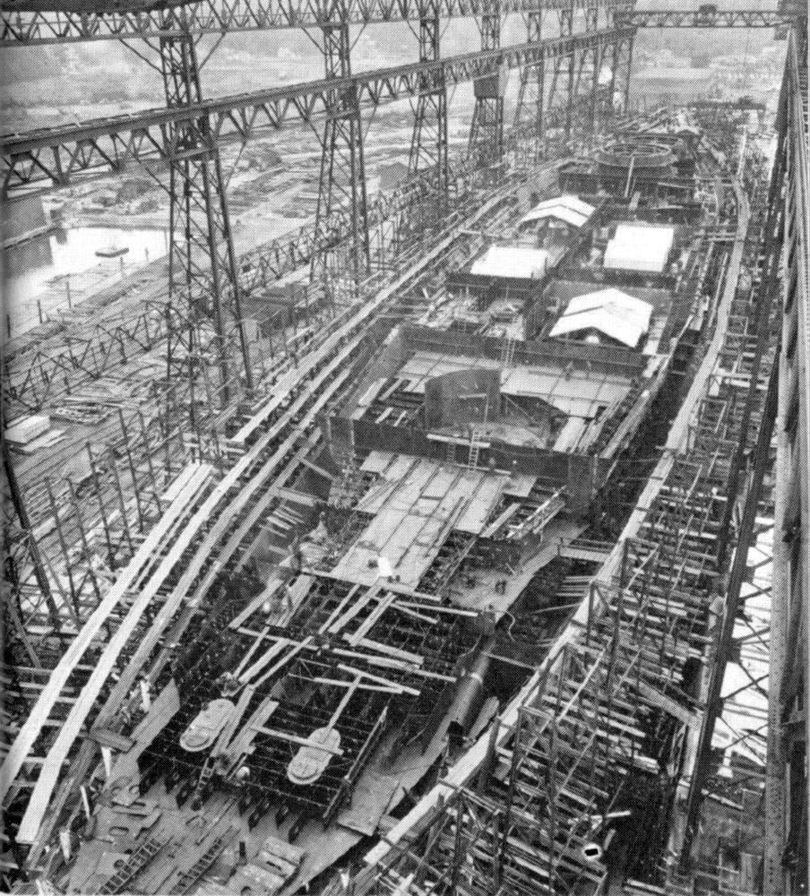
 | 237k | 3 October 1940 view of construction looking aft from the bow. The two forward turret barbettes are being erected and the covered areas just aft are protecting the machinery areas. | Official USN photo courtesy of Mike Green / Leeward Publications "SHIP'S DATA". | |
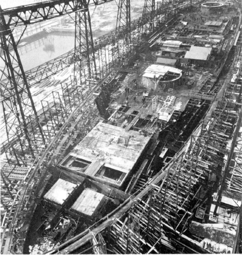
 | 248k | 3 October 1940 view of the construction looking forward from the stern area. Work is being done on the forward turret barbette installations along with machinery areas which are protected with coverings, but work has not yet began on #3 turret barbette. | Official USN photo courtesy of Mike Green / Leeward Publications "SHIP'S DATA". | |
 | 188k | 16 January 1941 view of construction looking aft from the bow. #2 turret barbette has been covered to protect the turret roller races that are being installed at this time. | Official USN photo courtesy of Mike Green / Leeward Publications "SHIP'S DATA". | |
 | 188k | 16 January 1941 view of construction as seen from the stern looking forward. | Official USN photo courtesy of Mike Green / Leeward Publications "SHIP'S DATA". | |
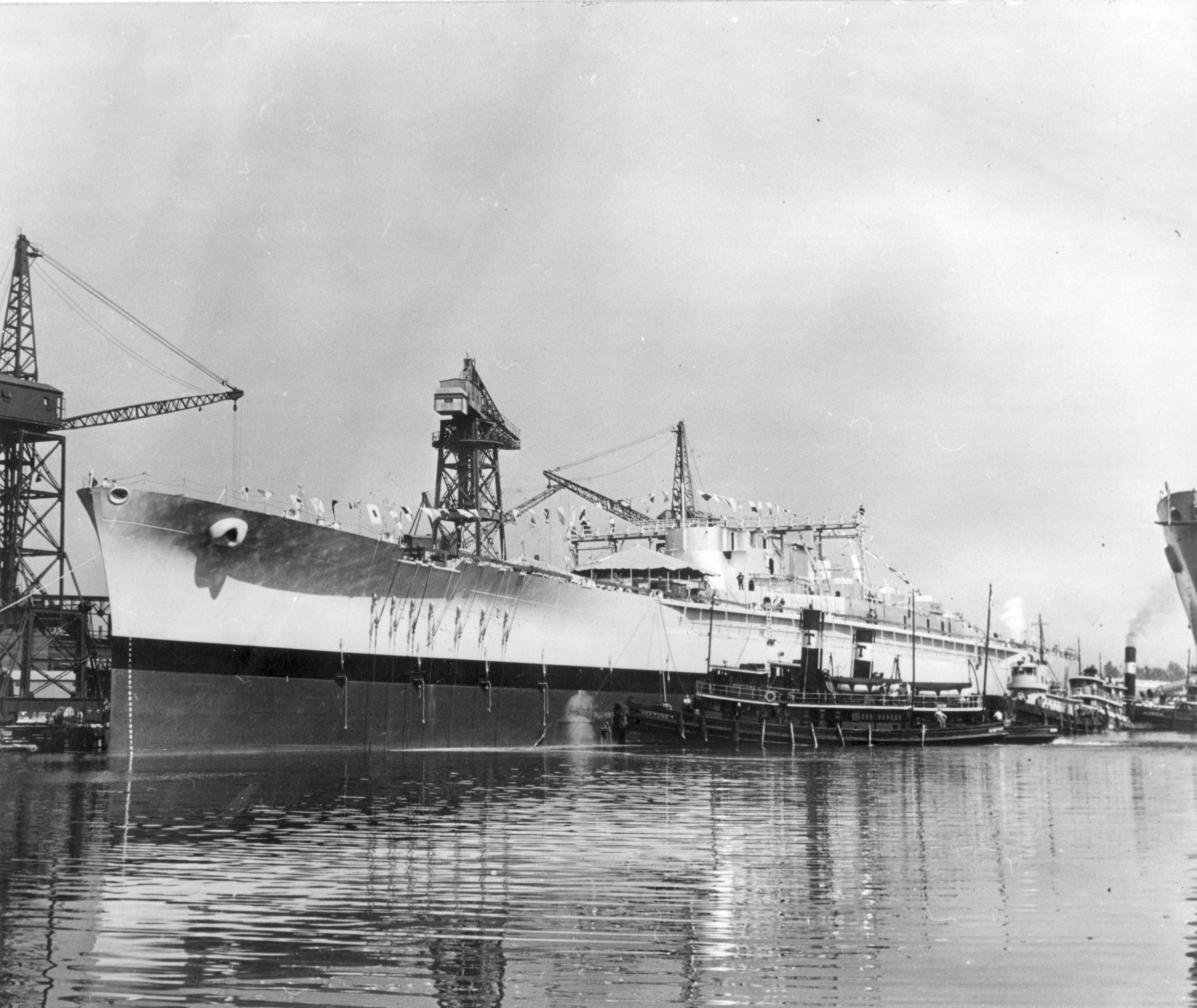
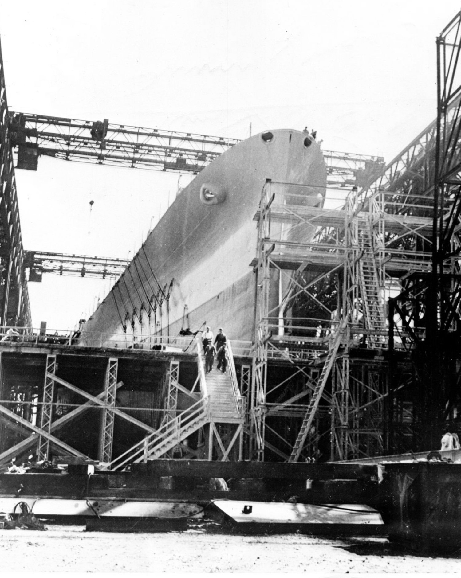 | 1.15k | "Finishing touches applied, the hull of the Massachusetts (BB-59) awaits launching ceremonies which will be held on 23 September. The 35,000 tn battleship will have firing power comparable to the North Carolina (BB-55) and Washington (BB-56), and is expected to travel in excess of 27 knots." | Photograph courtesy of Dale Hargrave. | |
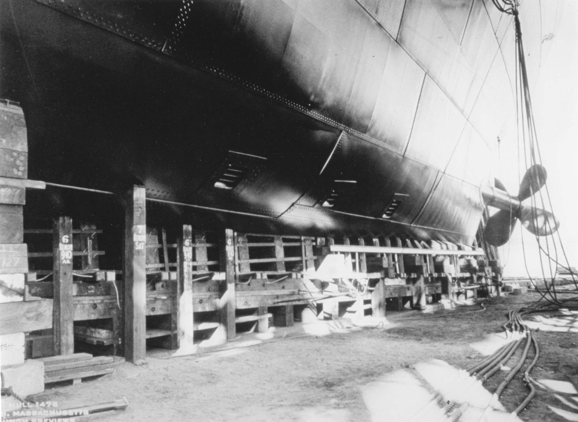
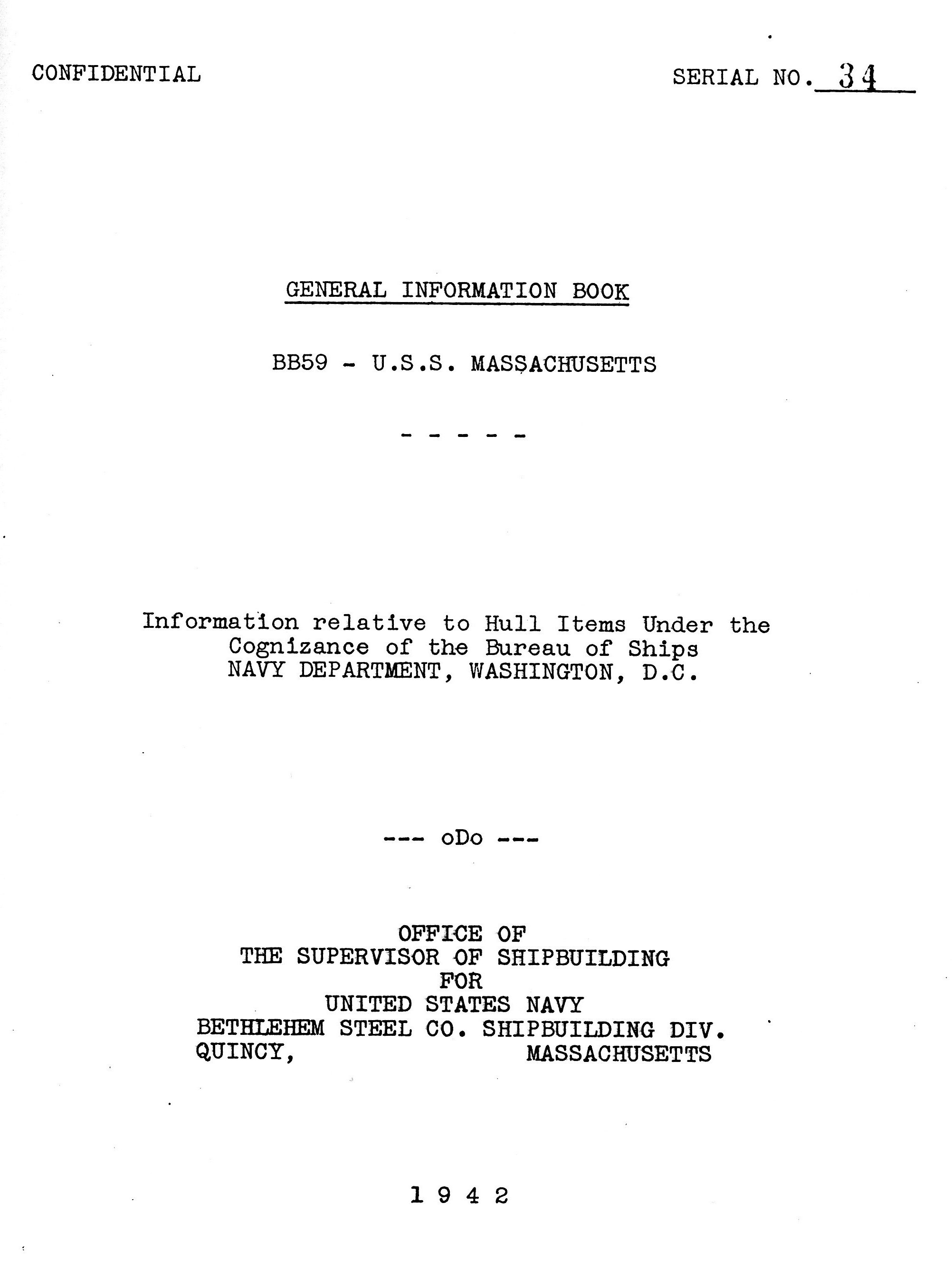
 | 265k | Pre launch preview of the stern section of the Massachusetts (BB-59) 23 September 1941. The ship is provided with two rudders, each of which is actuated by its own steering gear housed in separate compartments. The steering gears are exactly in duplicate and are independent except that synchronization of the two rudders is dependent upon synchronization of the two selsyn receivers as there is no mechanical or electrical coupling between the two rudder units. | USN photograph courtesy of Pieter Bakels. Sources: General Information Books of South Dakota and Massachusetts. Office of the Supervisor of Shipbuilding For The United States Navy, Bethlehem Steel Co. Shipbuilding Div., Quincy, Massachusetts. 1942. |
|
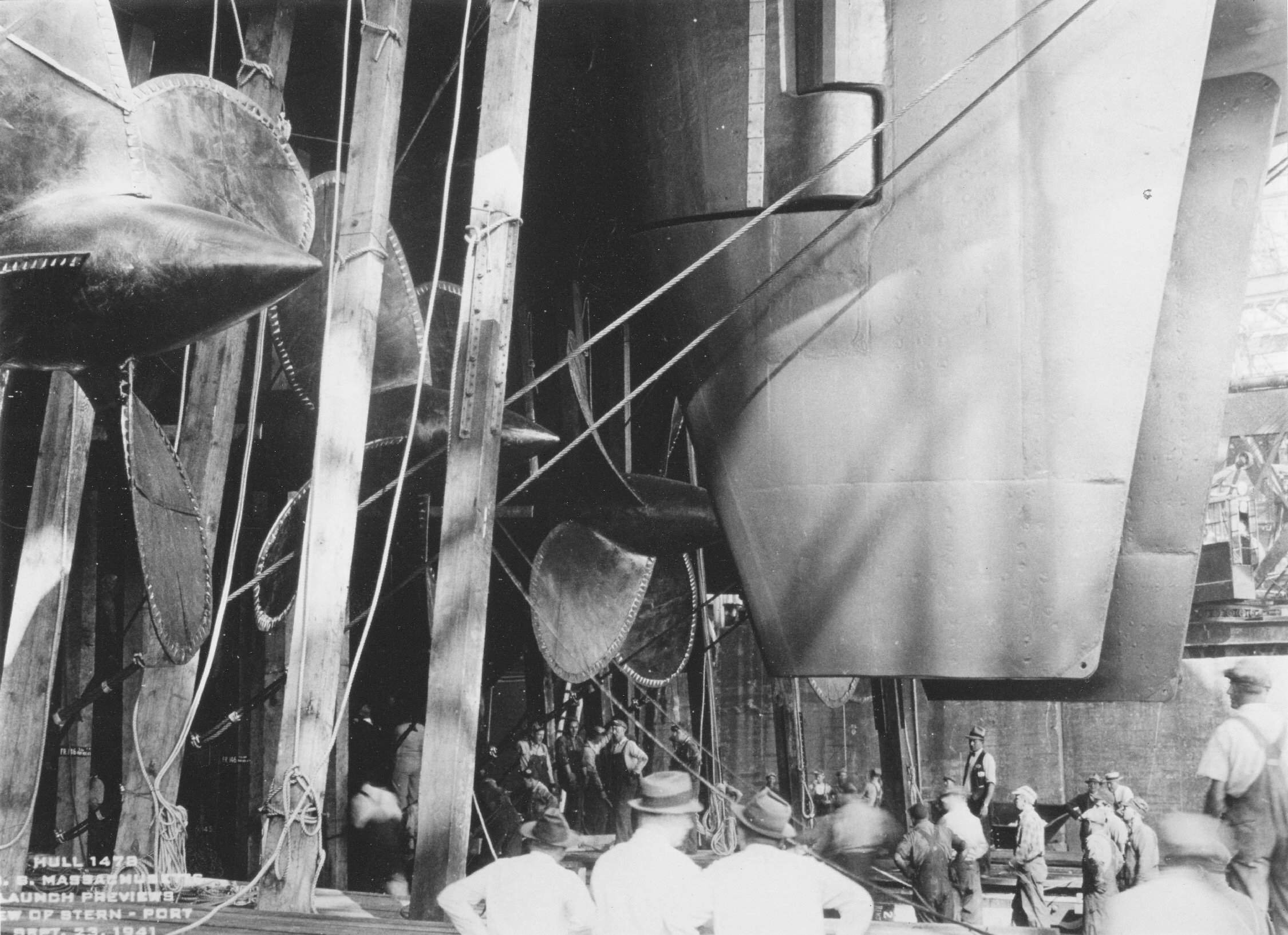
 | 208k | Pre launch preview of the stern section of the Massachusetts (BB-59) 23 September 1941. The steering Gear is of the electric-hydraulic type with a double arm cross-head and two pairs of ram cylinders, and two pump units, either one of which can be connected to the rams. The disconnected, or stand-by unit, is normally not running, but under critical conditions of navigation it may be started to permit quick change over if required. | USN photograph courtesy of Pieter Bakels. Sources: General Information Books of South Dakota (BB-57) and Massachusetts (BB-59). Office of the Supervisor of Shipbuilding For The United States Navy, Bethlehem Steel Co. Shipbuilding Div., Quincy, Massachusetts. 1942. |
|
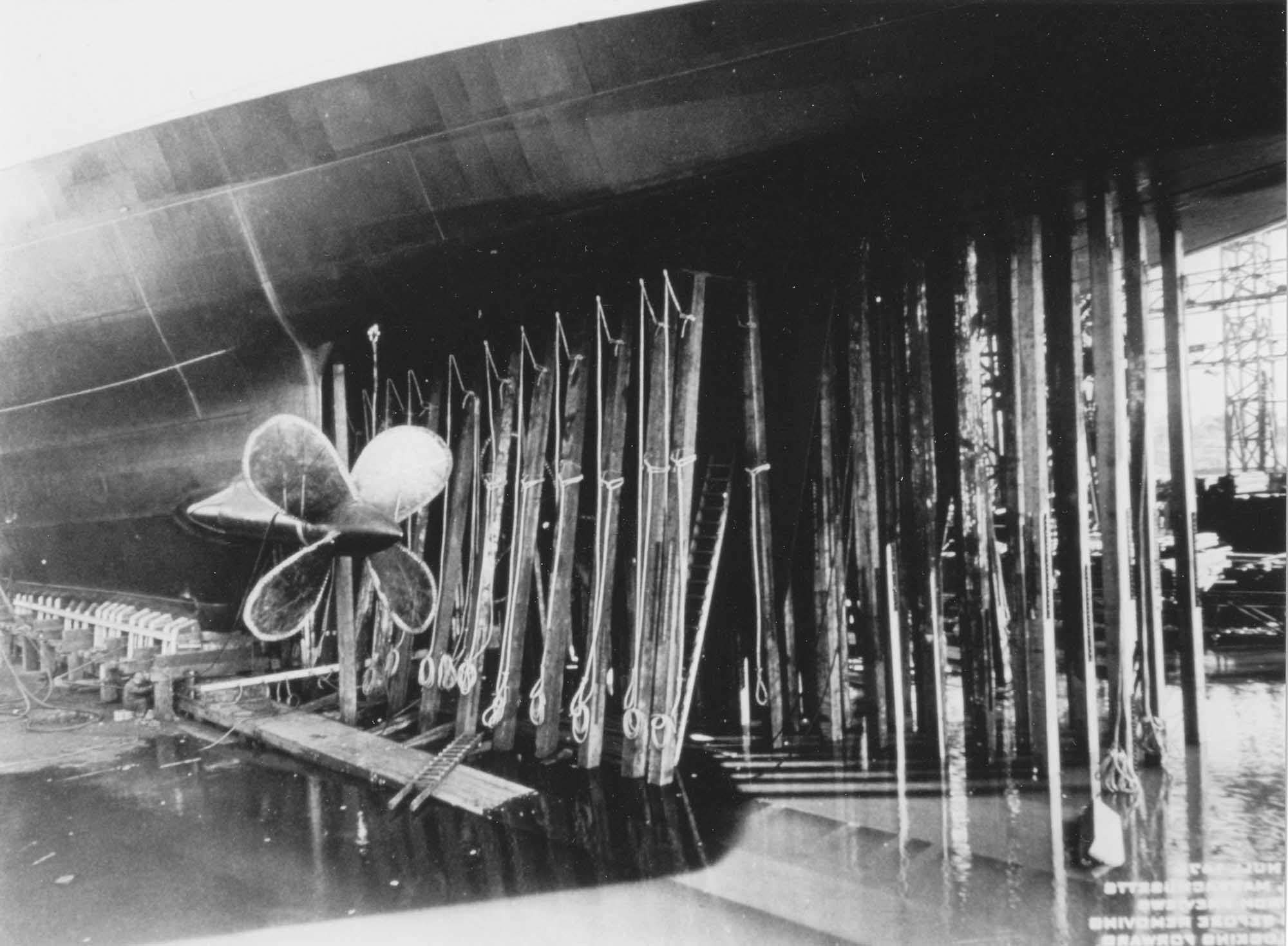
 | 224k | Pre launch preview of the stern section of the Massachusetts (BB-59) 23 September 1941. The rudders are of the balanced stream type. The area of one rudder is approximately 273 square feet. There are two rudders, each built up of a rudder main piece of cast steel, class "D" with stiffeners of plates run vertically and longitudinally and with sides of 60# and 30# plates and with a 60# doubler aft of the main piece, all welded together watertight. | USN photograph courtesy of Pieter Bakels. Sources: General Information Books of South Dakota (BB-57) and Massachusetts (BB-59). Office of the Supervisor of Shipbuilding For The United States Navy, Bethlehem Steel Co. Shipbuilding Div., Quincy, Massachusetts. 1942. |
|
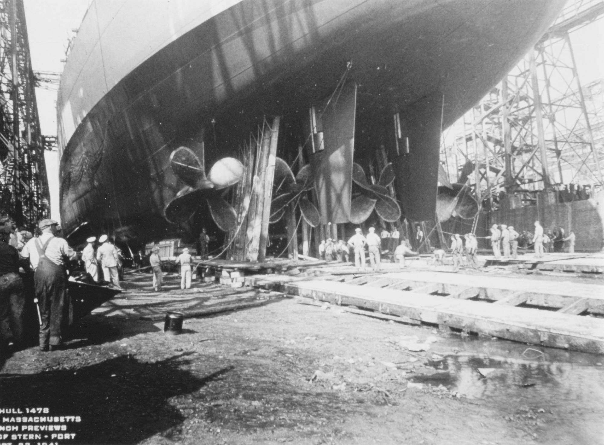
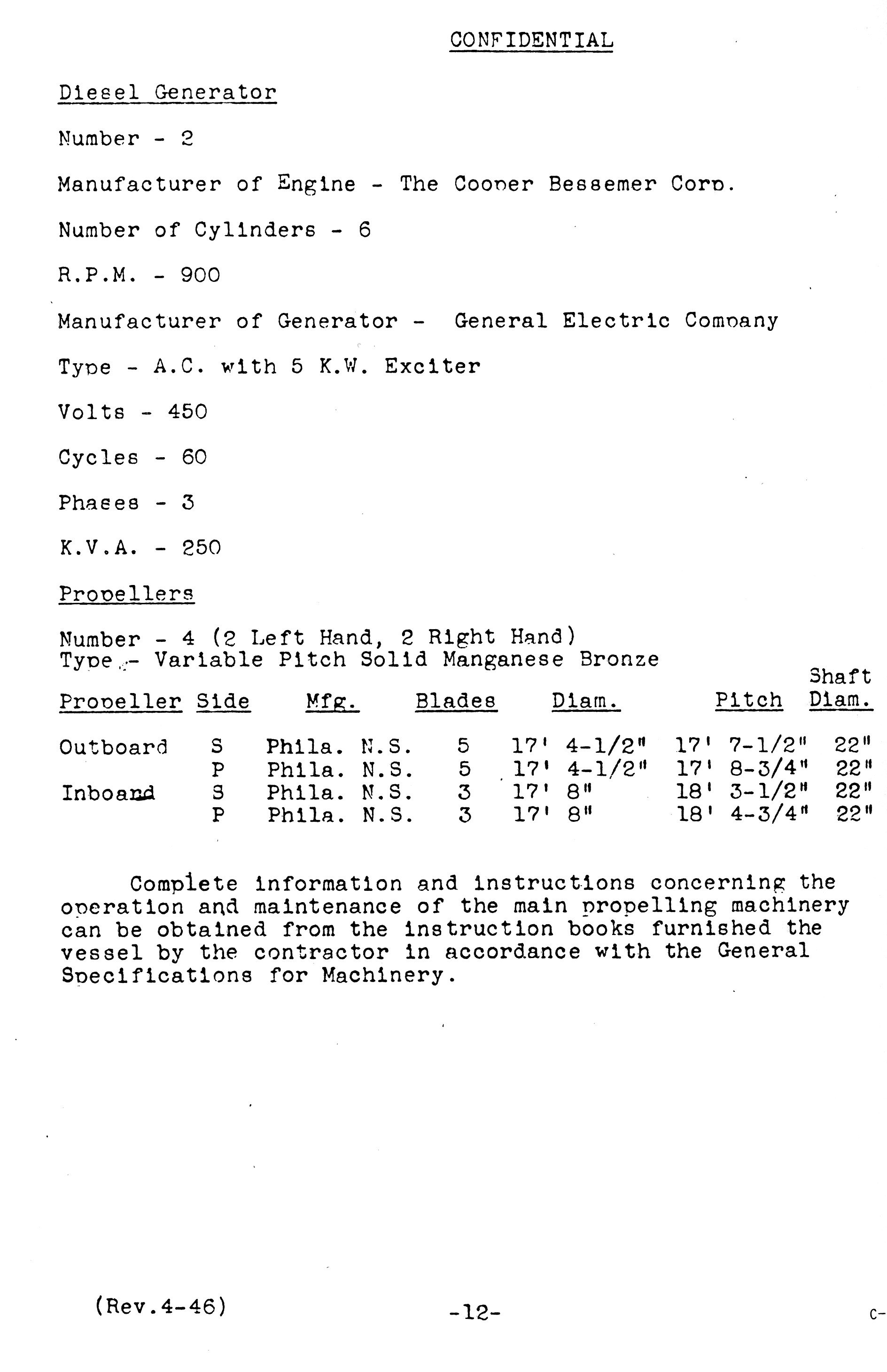
 | 345k | Pre launch preview of the stern section of the Massachusetts (BB-59) 23 September 1941. Massachusetts used 2 Left Hand and two Right Hand, Variable Pitch, Solid Manganese Bronze Propellers. The inboard propellers had 4 blades, diam. 17' 4-1/2 ". The outboard propellers had 4 blades, diam. 17' 8". Shaft diam: 22". |
USN photograph courtesy of Pieter Bakels. Sources: General Information Books of South Dakota (BB-57) and Massachusetts (BB-59). Office of the Supervisor of Shipbuilding For The United States Navy, Bethlehem Steel Co. Shipbuilding Div., Quincy, Massachusetts. 1942. | |
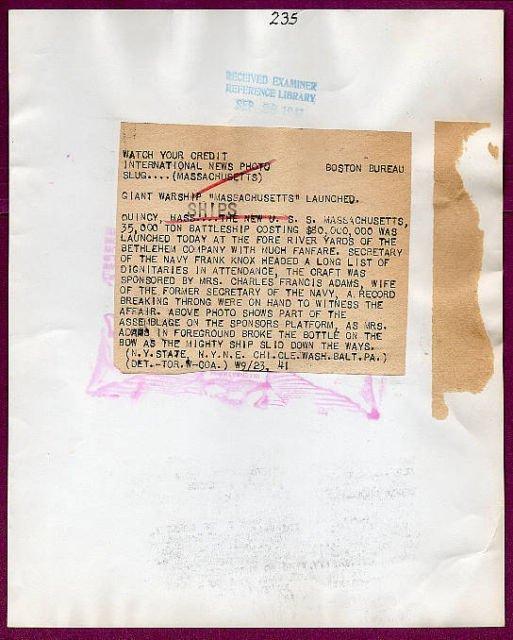
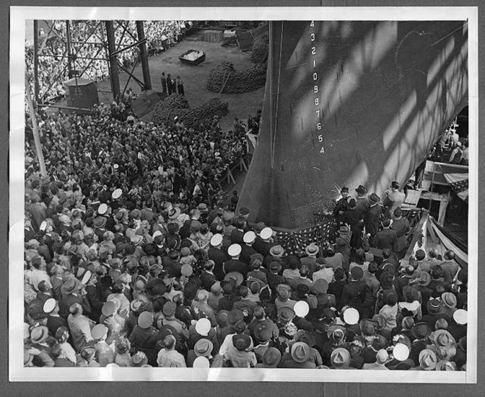 | 968k | GIANT WARSHIP MASSACHUSETTS (BB-59) LAUNCHED The new Massachusetts, 35,000 ton battleship costing $80,000,000 was launched today at the Fore River yards of the Bethlehem Company with much fanfare. Secretary of the Navy Frank Knox headed a long list of dignitaries at attendance. The craft was sponsored by Mrs. Charles Francis Adams, wife of the former Sec. of the navy. A record breaking throng were on hand to witness the affair. Above photo shows part of the assemblage on the sponsors platform as Mrs. Adams in the foreground broke the bottle on the bow as the mighty ship slid down the ways. | AP WIRE photo courtesy of Tommy Trampp. | |
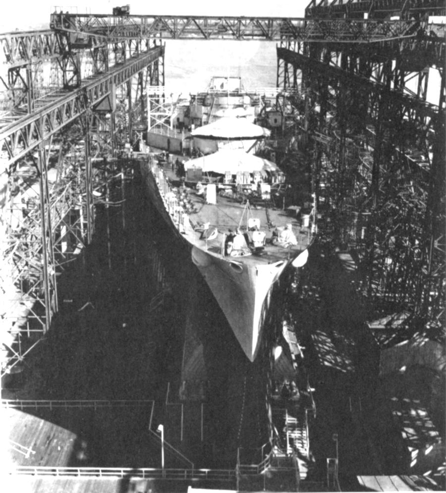 | 139k | Massachusetts (BB-59) on 23 September 1941 just prior to launching. Note temporary bridge erected over the conning tower to assist in guiding tugs which will move her to the fitting out basin after being launched. | Official USN photo courtesy of Mike Green / Leeward Publications "SHIP'S DATA". | |
 015977 | 525k | QUINCY, MASS. ANOTHER LINK IN UNCLE SAMS FIRST LINE OF DEFENSE The Massachusetts (BB-59), 35,000-ton battleship and the newest addition to the United States Fleet, as she slid down the ways at the Bethlehem Steel Co. Fore River yard today. IN LIKE FLINT As the huge hull cleared the ways, an overhead crane swung into place the keel for the Flint (CL-97), a new cruiser. The Massachusetts will have a main battery of nine 16-inch guns, mounted in three turrets, as well as a battery of the latest type anti-aircraft and secondary broadside guns. The new battleship is the fourth to be launched under the capital ship expansion program. There she goes - down the ways, flag draped bow billowing in the breeze, 23 September 1941. | A. P. Wirephoto. Image and text provided by Library of Congress, Washington, DC. Photo & text by Evening Star. [volume] (Washington, D.C.) 1854-1972, 23 September 1941, Image 1, courtesy of chroniclingamerica.loc.gov. USN photo courtesy of Pieter Bakels. | |
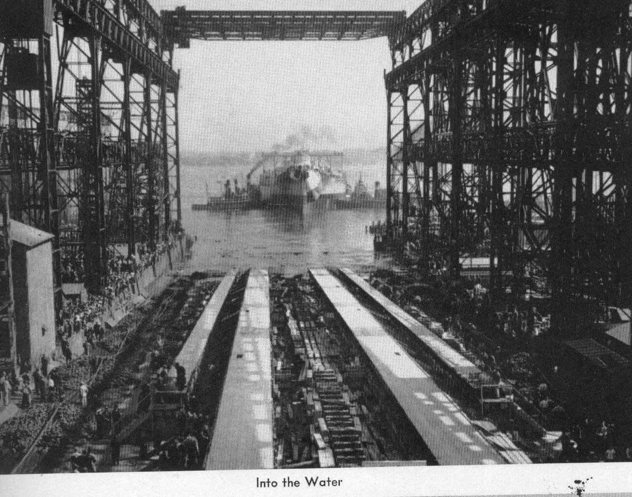 | 521k | Into the water. | USN photo courtesy of James E. Hesson plank-owner of the Massachusetts (BB-59). Photo submitted in his memory by his son, Joe Hesson. | |
 | 391k | Sign of the times for the Massachusetts (BB-59). | Photo courtesy of Authors Collection (i.e. forgot the source). | |
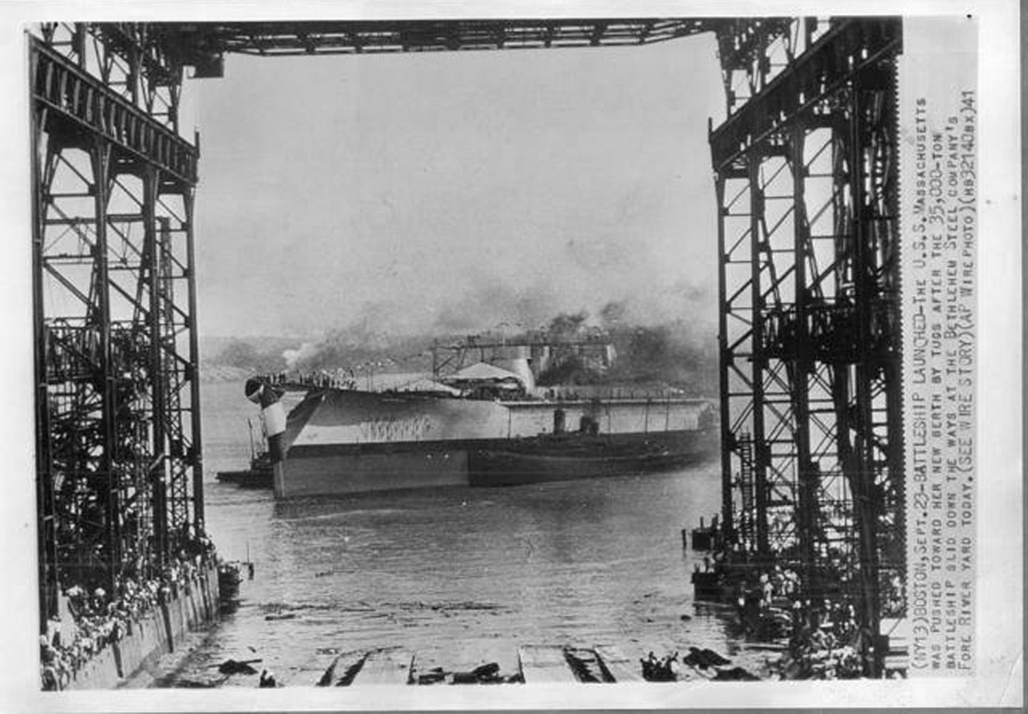 | 620k | BATTLESHIP LAUNCHED The Massachusetts (BB-59) was pushed towards her new berth by tugs after the 35,000 ton battleship slid down the ways at the Bethlehem Steel Company Fore River Yard today 23 September 1941. | AP WIRE photo courtesy of Tommy Trampp. | |
 | 492k | Just after her launch, 23 September 1941. Among the tugboats attending is the Neptune, in the foreground. | USN photo courtesy of Pieter Bakels. | |
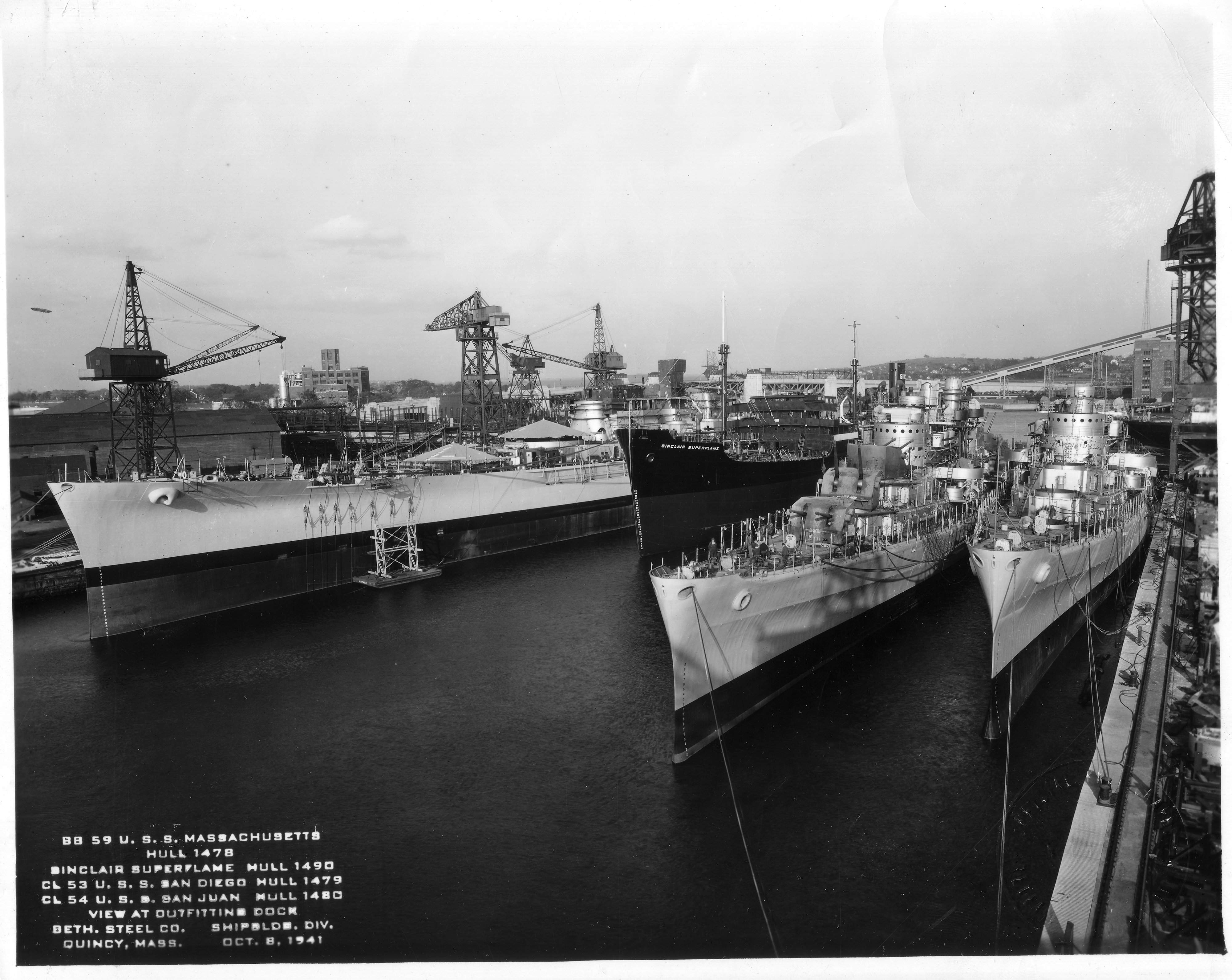 | 867k | Hull # 1478, otherwise known as Massachusetts (BB-59), and some new additions to Uncle Sam's arsenal rise from the outfitting dock waters of Bethlehem Steel, Quincy, MA. on 8 October 1941. To the right of Massachusetts is Sinclar Superflame, Hull # 1490, San Diego (CL-53), Hull # 1479 & San Juan (CL-54), Hull # 1480. | Bureau of Ships photo # 29559, courtesy of Pieter Bakels. | |
 | 392k | A many bladed propeller test was tried out in the following sources: "Battleships", US BB's in WWII/Dulin & Garzke, Anna,MD.,various editions. U.S. Battleships: An Illustrated Design History by Norman Friedman. page 287: ...."The designers cut the necessary area out of the bottom of the hull, forming a tunnel". "In its case, the chief risk was vibration due to interaction between propellers and skegs".(...) Page 294: "All ships but Indiana (BB-58) were completed with four-bladed propellers on each shaft". (...) "Model tests showed that five-bladed props inboard would be superior"(...)"Vibration trials (Indiana) in September of 1942 showed this arrangement superior to the 4 blade outboard/3 blade inboard combination installed aboard the South Dakota (BB-57) and the 5/4 combination was installed aboard the Massachusetts (BB-59) (1944)"(...) , etc....... Massachusetts, (Ship's Data)-Leeward publications, Anna, MD. 1979, page 22: (...) "A variety of propeller configurations was tried, in an effort to reduce vibration at high speed"(...) (...) "Alabama (BB-60) trials showed severe fore and aft vibrations due to inboard strut-supported propellers, and rather less severe athwardship vibrations due to the outboard skeg-supported ones; as a result the inboard four bladed propellers were replaced by three-bladed ones". "Five bladed propellers were also tried"(...) | USN photo courtesy of Pieter Bakels. | |
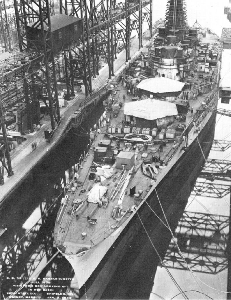 | 168k | Massachusetts (BB-59) on 3 January 1942 being fitted out. No armament is in place at this time. | Official USN photo courtesy of Mike Green / Leeward Publications "SHIP'S DATA". | |
 | 159k | Massachusetts (BB-59) on 1 May 1942 being fitted out. | USN photo courtesy of David Buell. | |
 | 500k | All dressed up and ready to go, minus airplanes. | USN photo courtesy of James E. Hesson, plank-owner of the Massachusetts (BB-59). Photo submitted in his memory by his son, Joe Hesson. | |
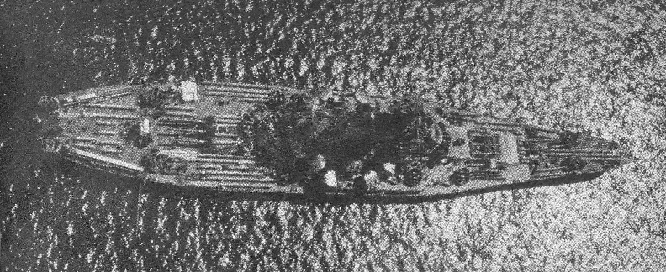
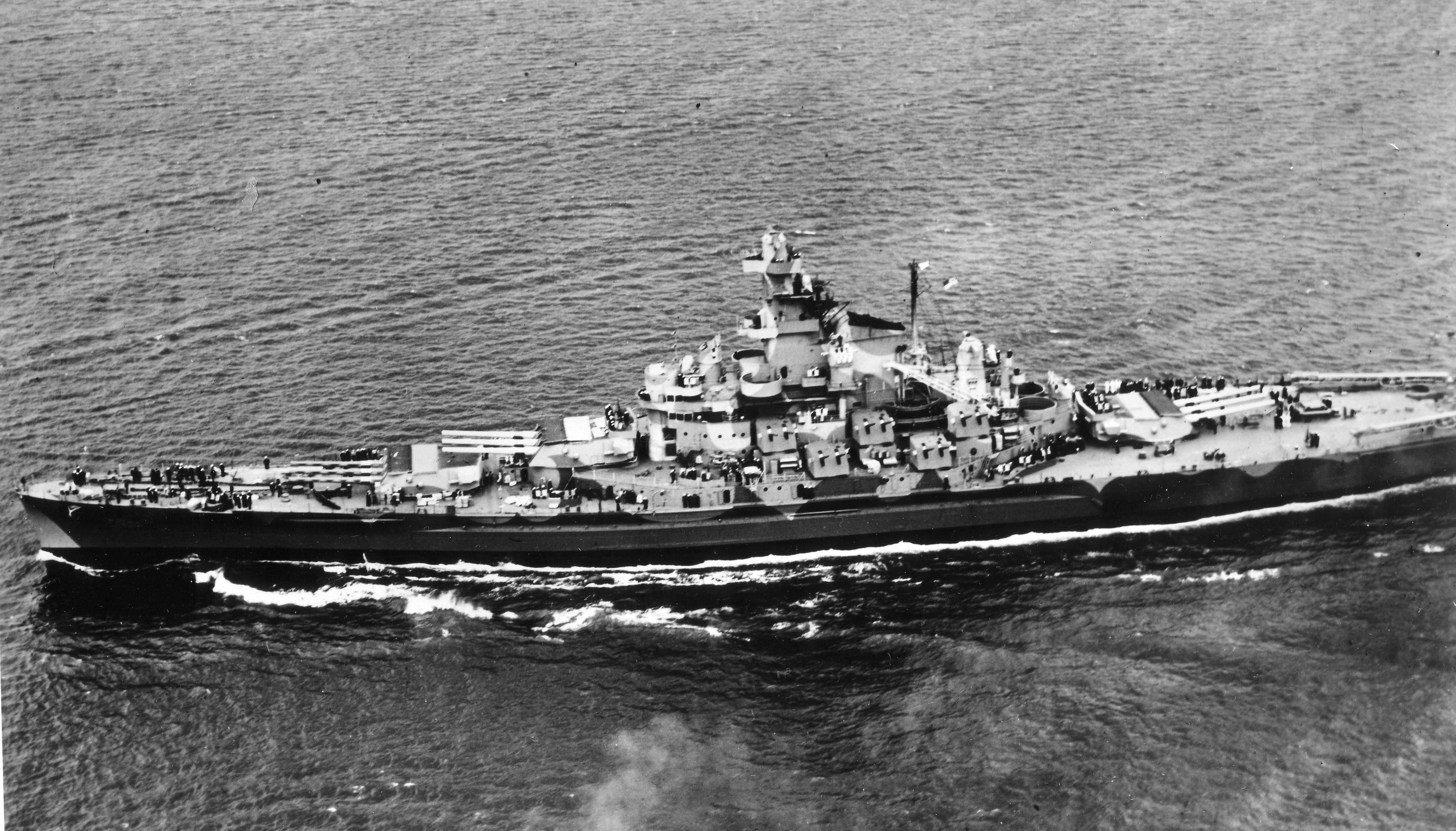
 | 417k | Entering Boston Harbor, Massachusetts, after leaving the Fore River Shipyard at Quincy, 12 May 1942. Photographed from an altitude of approximately 400 feet. Note harbor defense net system at top, with a Net Tender (AN) in attendance. | Naval History and Heritage Command # NH 97254, from the collections of the Naval Historical Center. | |
 | 759k | Boston Harbor tugboats and small craft escort the Massachusetts (BB-59) on 12 May 1942 after her commissioning. | USN photo courtesy of Pieter Bakels. | |
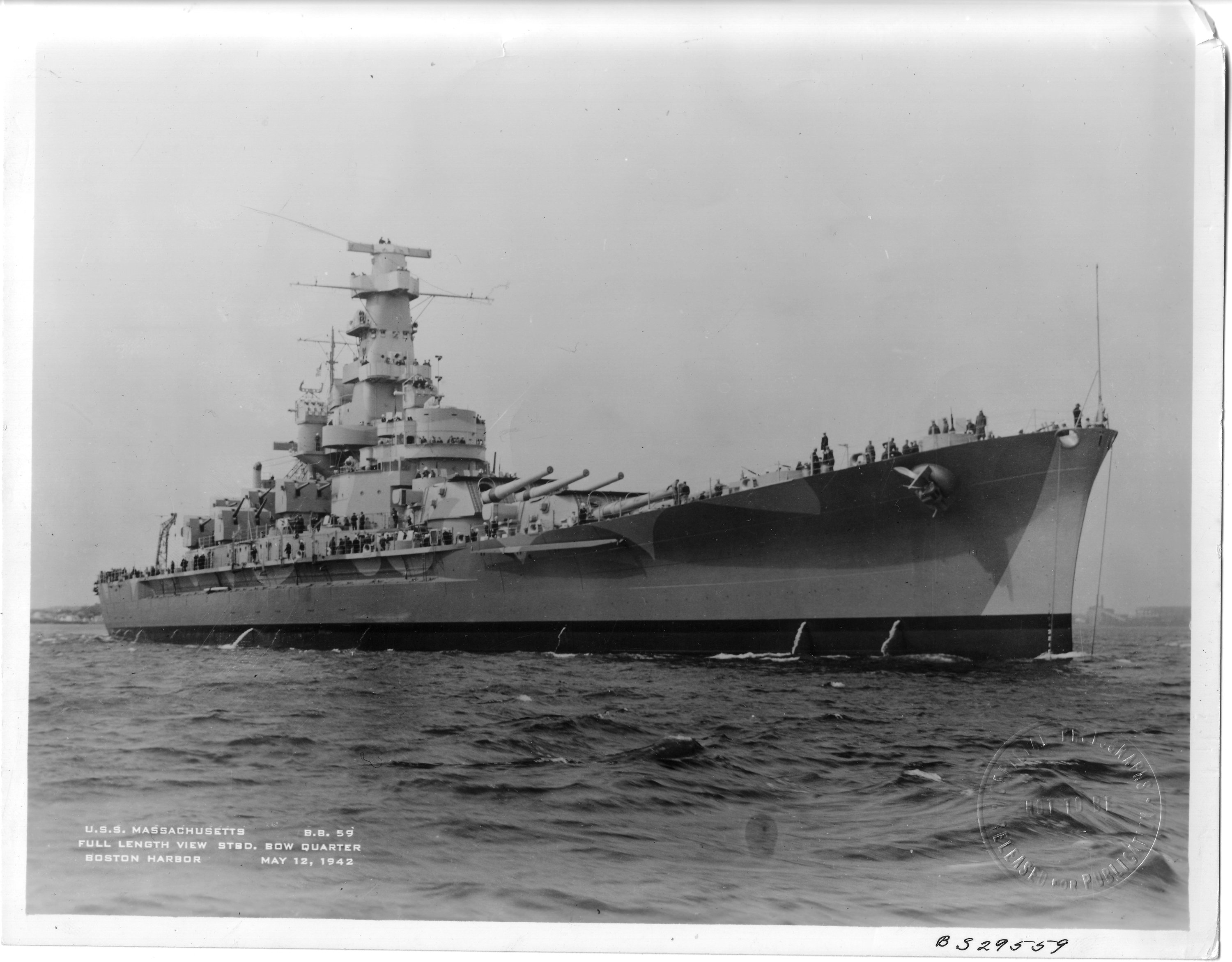 | 650k | Boston Harbor is full of Massachusetts (BB-59) in this lengthy starboard bow quarter view on 12 May 1942 after being commissioned this day. | Bureau of Ships photo # 29559, courtesy of Pieter Bakels. | |
 | 1.20k | Clean lines along with no radar, incomplete light weight A.A. armament and no planes mean that she's not quite ready for sea. Port side view underway during her commissioning day. | USN photo courtesy of Pieter Bakels. | |
| July 1942 - February 1943 / War in the Atlantic |
||||
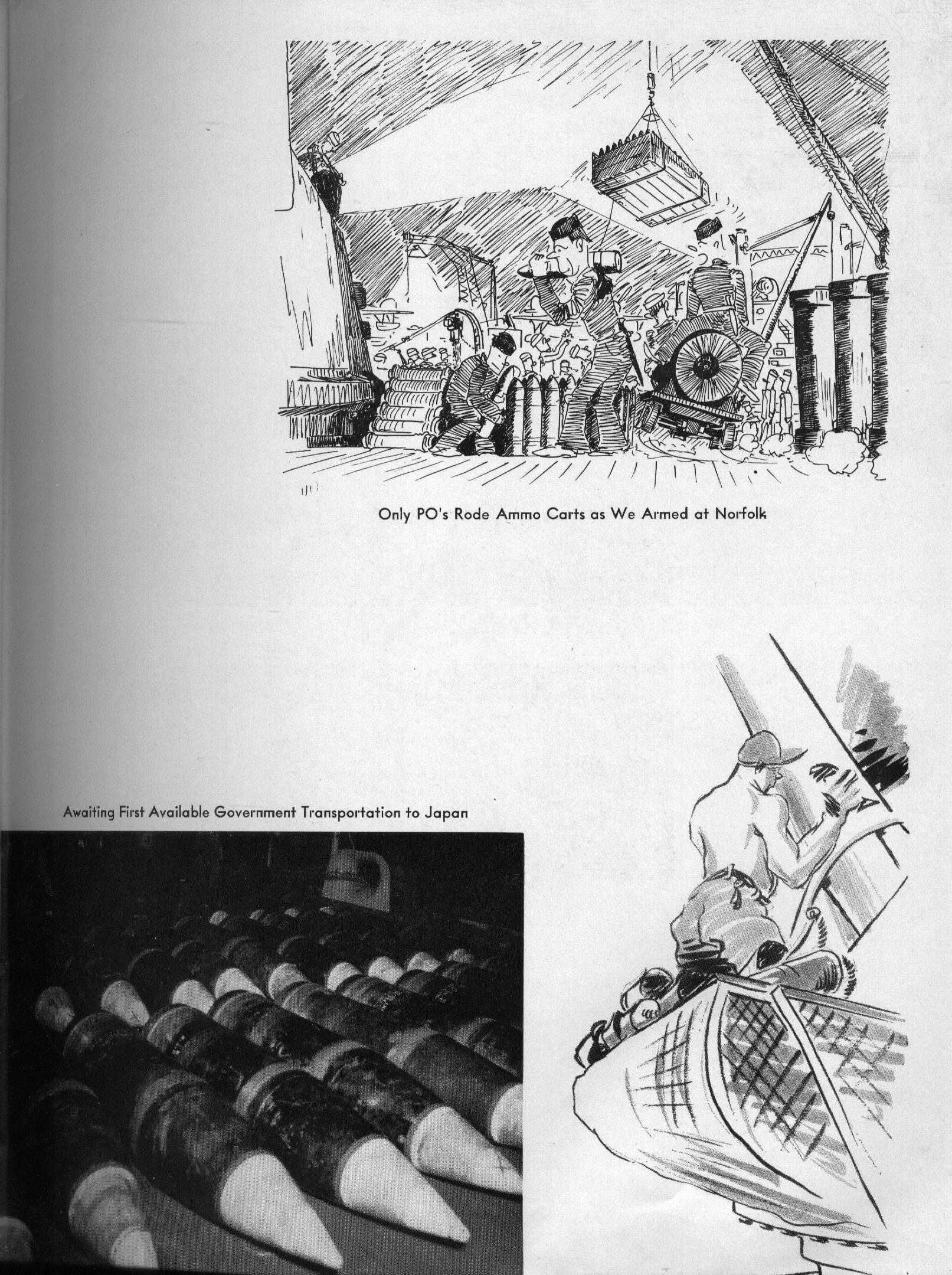 | 600k | Only PO's rode ammo carts as we armed at Norfolk. | USN photo courtesy of James E. Hesson, plank-owner of the Massachusetts (BB-59). Photo submitted in his memory by his son, Joe Hesson. | |
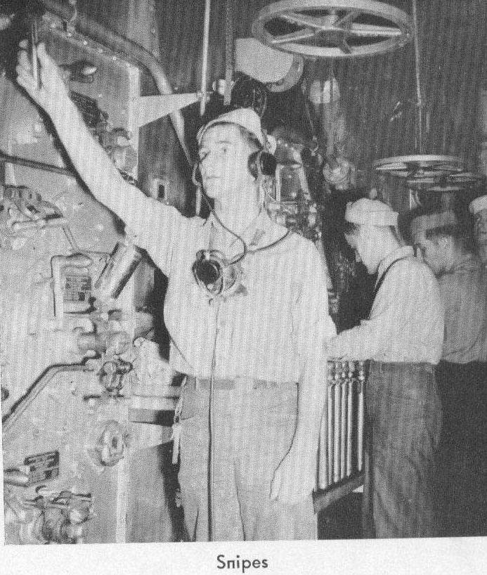 | 141k | Below decks scene: Snipes. | USN photo courtesy of James E. Hesson, plank-owner of the Massachusetts (BB-59). Photo submitted in his memory by his son, Joe Hesson. | |
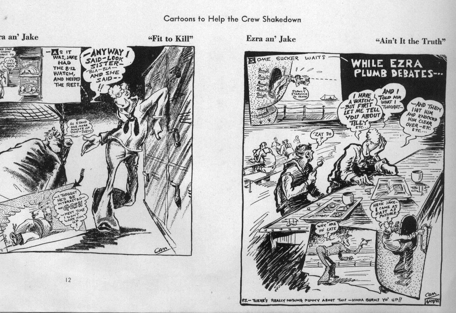 | 403k | Cartoons to help the crew shakedown. | USN photo courtesy of James E. Hesson, plank-owner of the Massachusetts (BB-59). Photo submitted in his memory by his son, Joe Hesson. | |
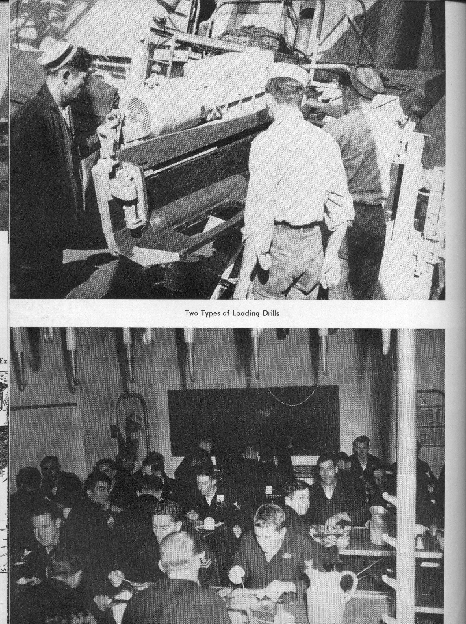 | 750k | Two types of loading drills. | USN photo courtesy of James E. Hesson, plank-owner of the Massachusetts (BB-59). Photo submitted in his memory by his son, Joe Hesson. | |
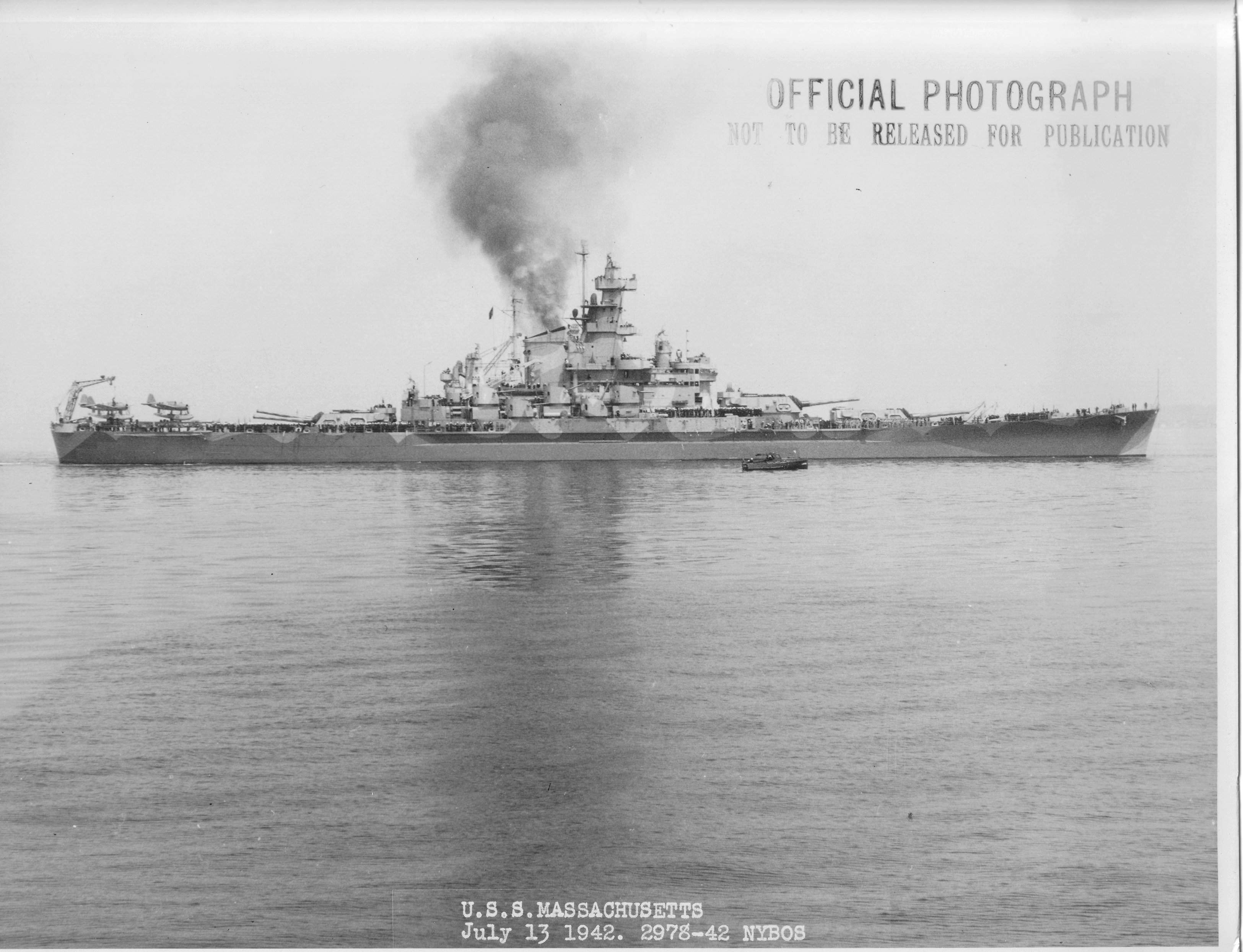 | 513k | Massachusetts (BB-59), starboard side view with camouflage paint during shakedown trials on 13 July 1942. | USN photo #2978-42 courtesy Pieter Bakels. | |
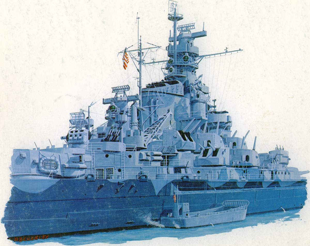
 | 101k | Massachusetts (BB-59) July 1942, in Measure 12. Note SC radar on foremast, Mk.3 and IFF on Spot I and Mk.4 atop MK.37's. | Drawing courtesy of A.B. Cheley & submitted by Pieter Bakels. | |
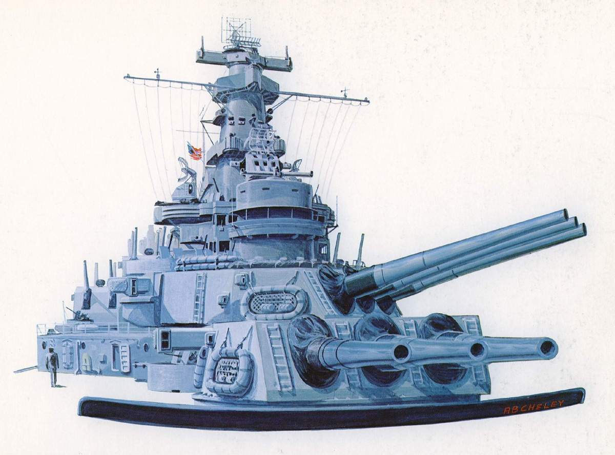
 | 131k | Artwork showing the amidships of Massachusetts (BB-59) and her anti-aircraft battery. | Drawing courtesy of A.B. Cheley & submitted by Pieter Bakels. | |
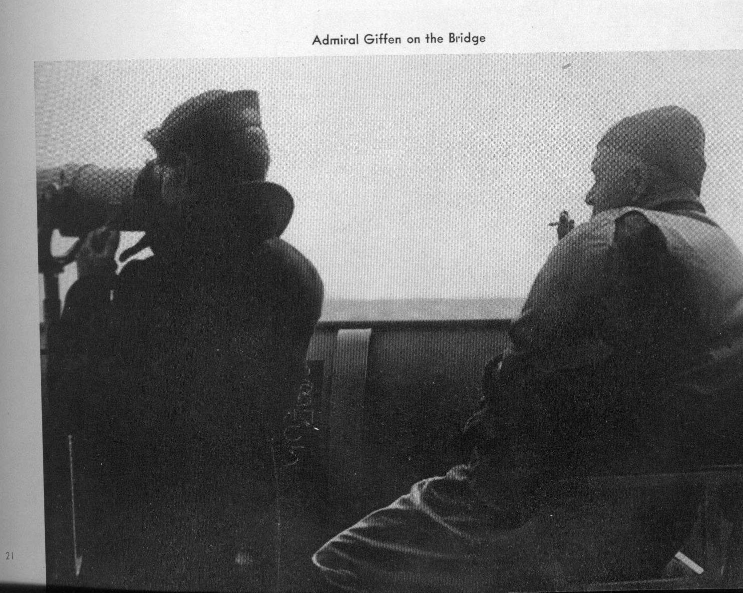 | 397k | Admiral Giffen on the bridge. | USN photo courtesy of James E. Hesson, plank-owner of the Massachusetts (BB-59). Photo submitted in his memory by his son, Joe Hesson. | |
 | 311k | Sea stories of Casablanca. | USN photo courtesy of James E. Hesson, plank-owner of the Massachusetts (BB-59). Photo submitted in his memory by his son, Joe Hesson. | |
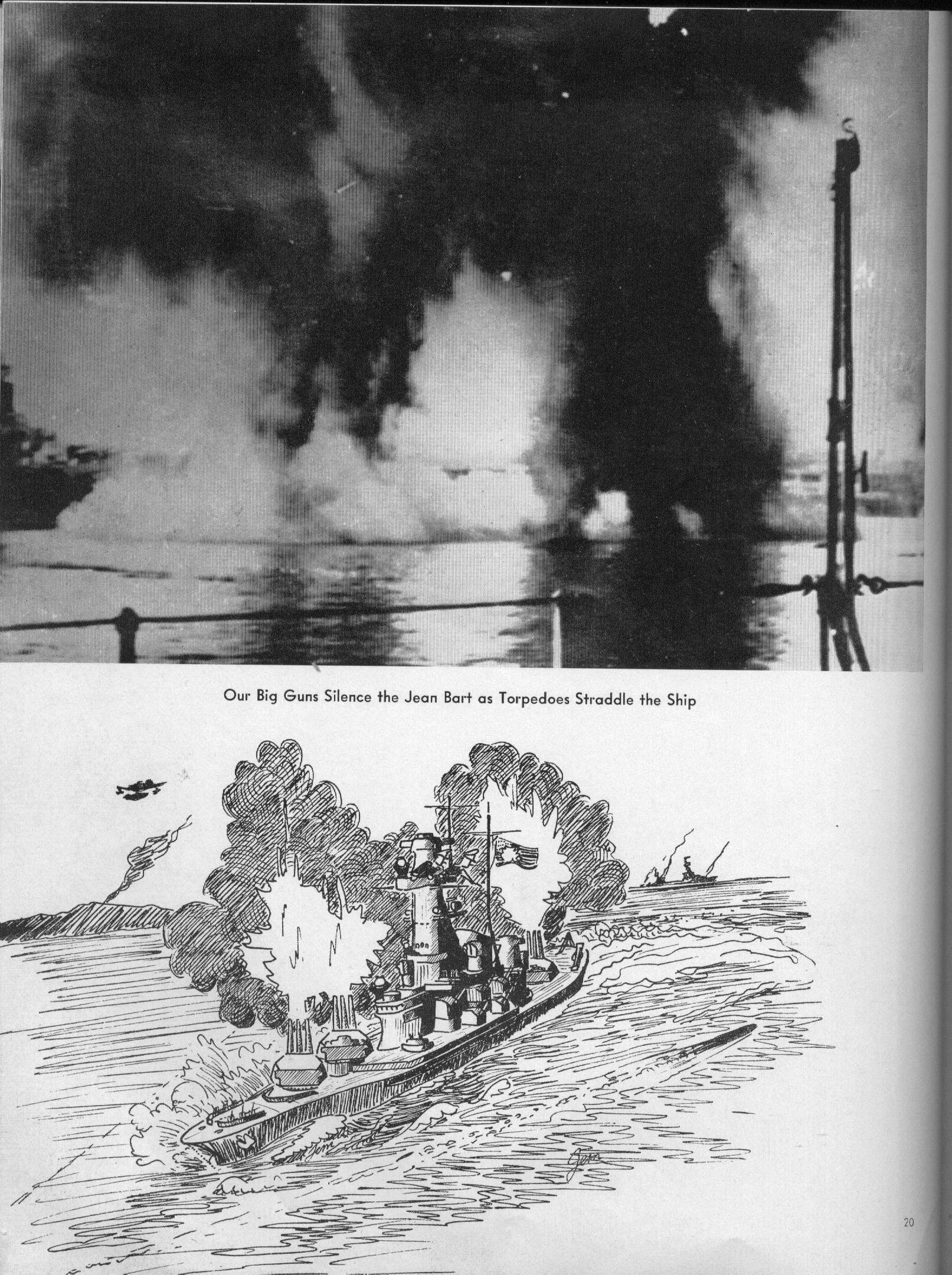 | 683k | Our big guns silence the Jean Bart as torpedoes straddle the ship. | USN photo courtesy of James E. Hesson, plank-owner of the Massachusetts (BB-59). Photo submitted in his memory by his son, Joe Hesson. | |
 |
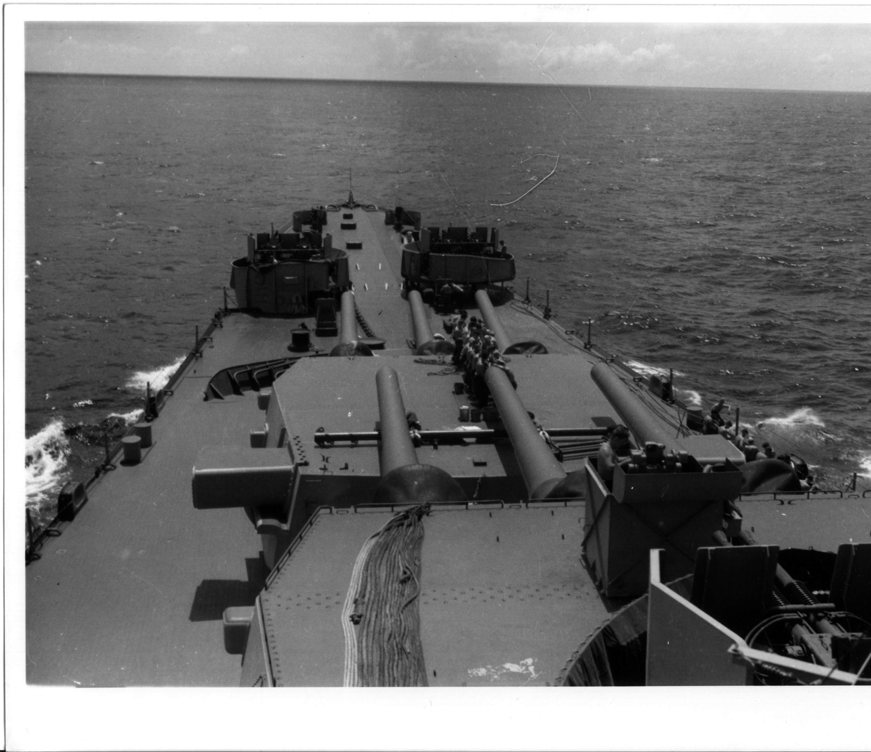
313k | A view forward from the 20MM tub on top of turret #2 as Massachusetts (BB-59) heads into the sun on 4 November 1942, just before the Battle of Casablanca. "Lead Dammit Lead" is stenciled on the 20mm gun shield and Texas (BB-35) is at left, in the distance. | USN photo # 80-G-264953 now in the collection of the US National Archives in College Park, Maryland, courtesy of Tracy White @ Researcher @ Large. | |
 | 65k | View looking forward from the ship's after deck, during a lull in the Battle of Casablanca, 8 November 1942. Note: 16"/45 guns of her after turret; 20mm gun at left with "Lead, Dammit, Lead" printed on its shield; FC & FD radar antennas atop her gun directors; two large National Ensigns flying from her masts. | Naval History and Heritage Command # NH 84534, from the collections of the Naval Historical Center. | |
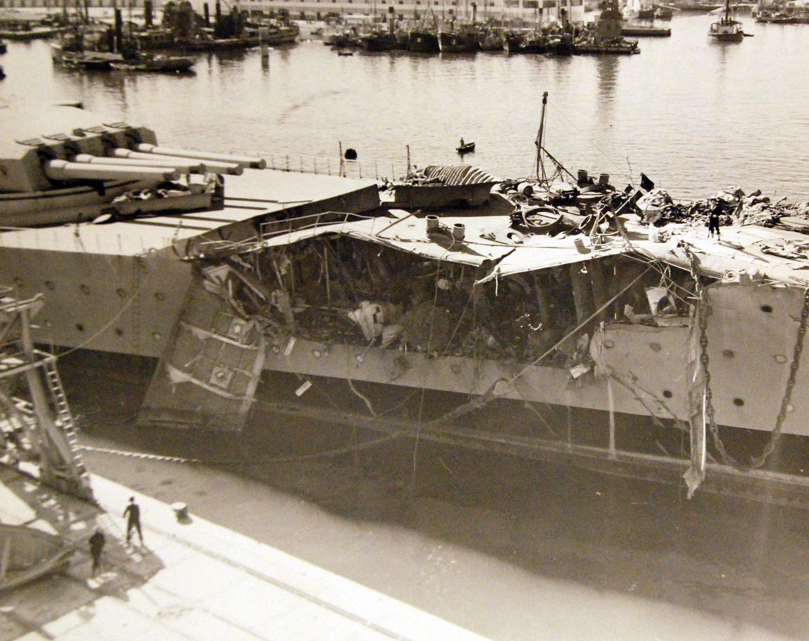
 | 144k | November 1942: Jean Bart at Casablanca, Morocco showing battle damage received in her engagement with Massachusetts (BB-59) and from aerial bombing during the Operation Torch landings November 8-11, 1942. | USN photograph courtesy of maritimequest.com. Insert photo # Lot-11582-16 courtesy of National Museum of the U.S. Navy via flicker.com. |
|
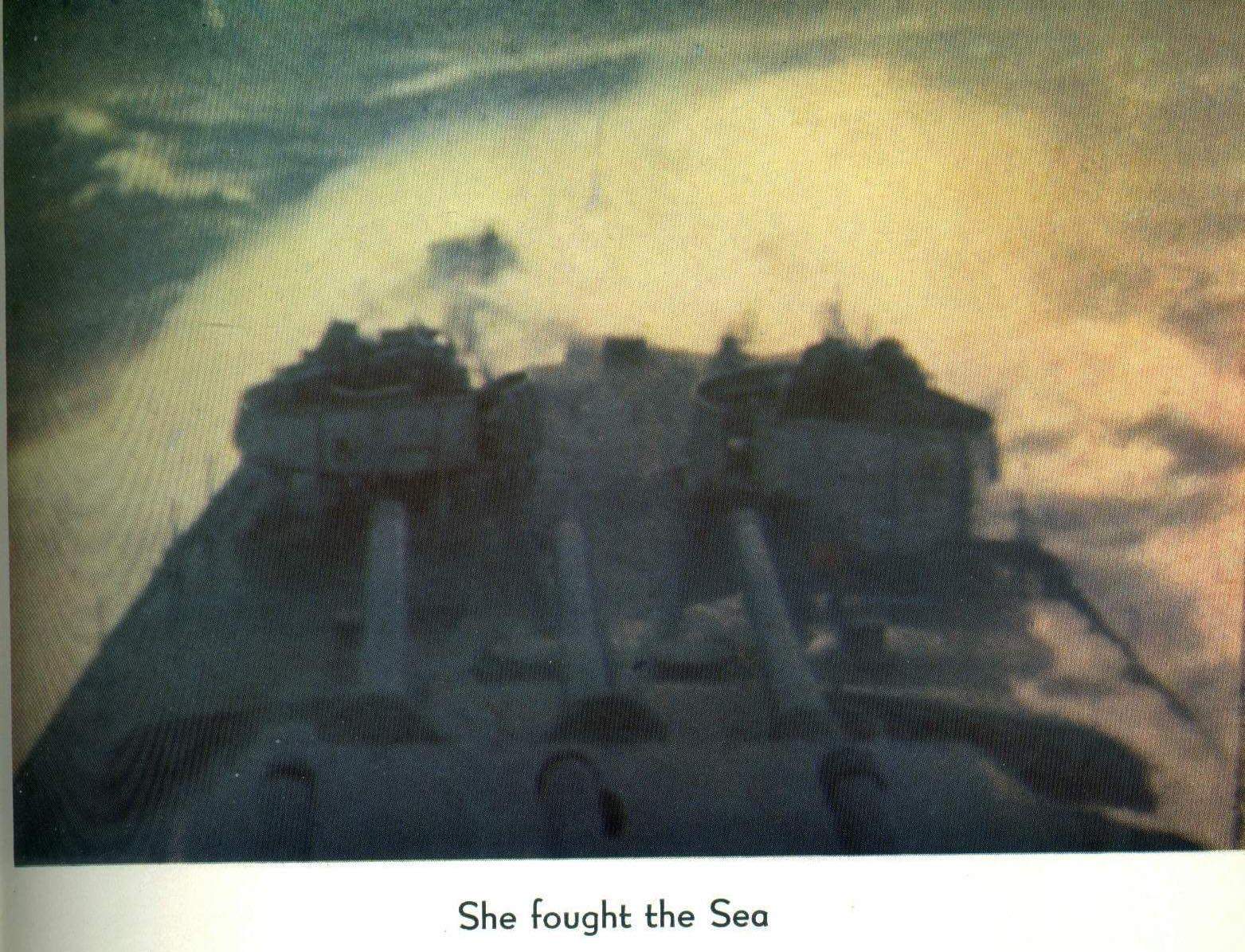 | 442k | She fought the sea. | USN photo courtesy of James E. Hesson, plank-owner of the Massachusetts (BB-59). Photo submitted in his memory by his son, Joe Hesson. | |
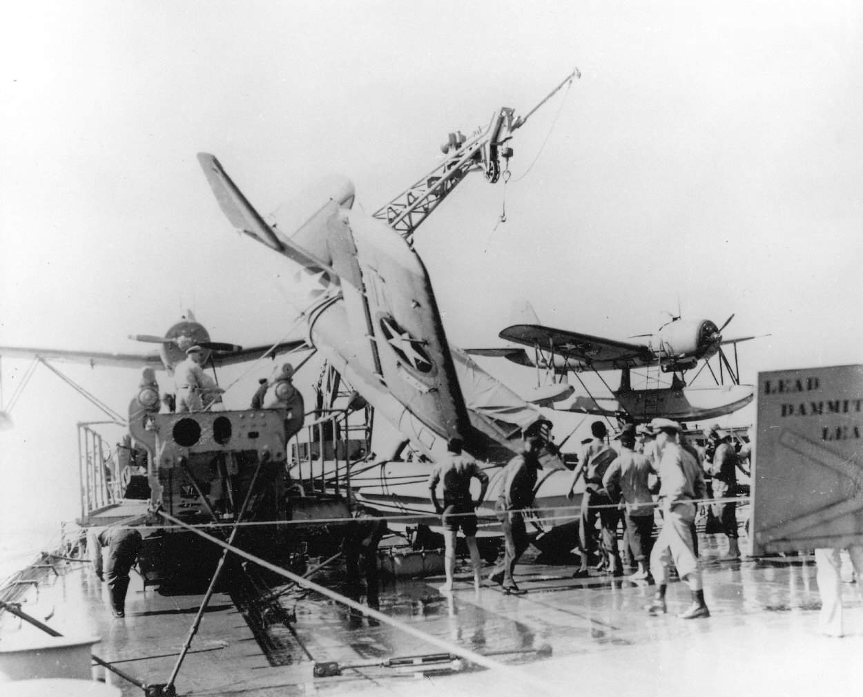 | 104k | Taken after a storm that wrecked one of the aircraft aboard Massachusetts (BB-59) during Operation Torch in the Atlantic. | USN photograph courtesy of Pieter Bakels. | |
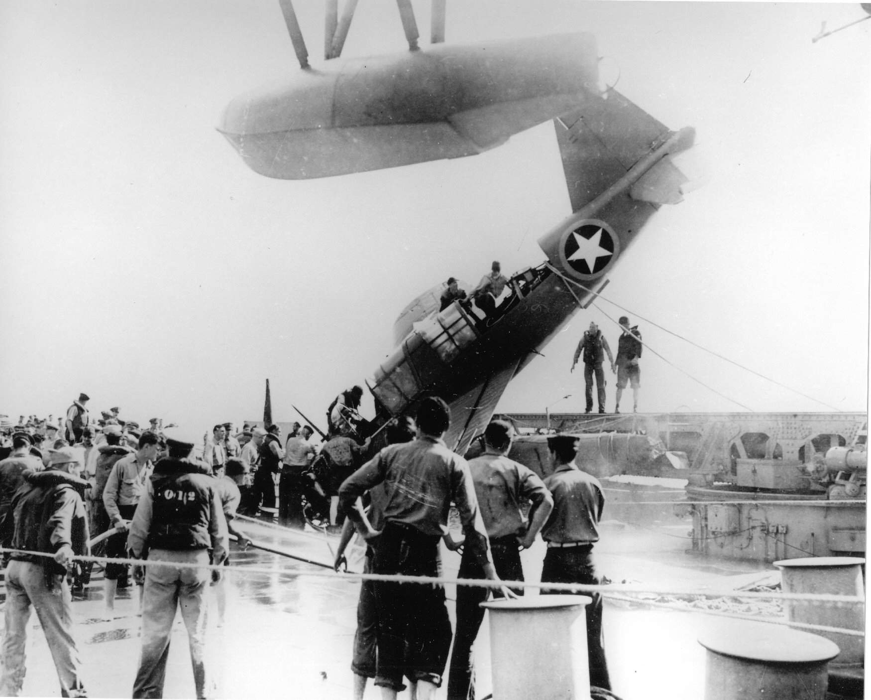 | 169k | Taken after a storm that wrecked one of the aircraft aboard Massachusetts (BB-59) during Operation Torch in the Atlantic. | USN photograph courtesy of Pieter Bakels. | |
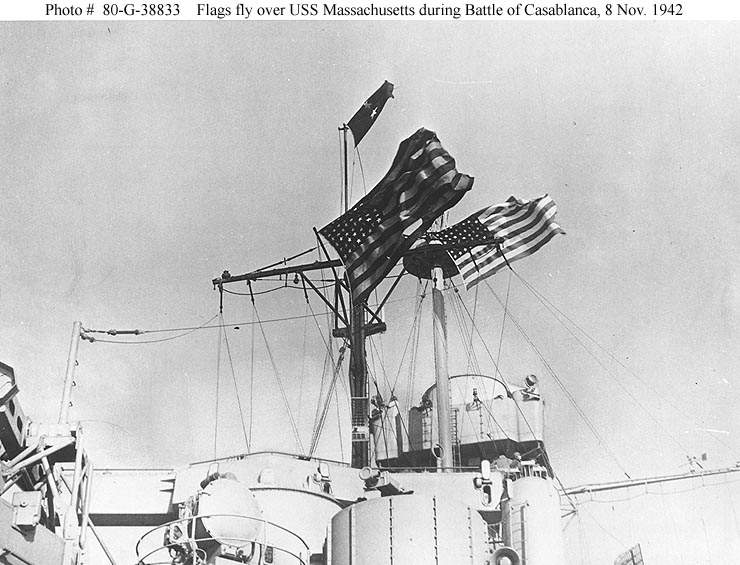 | 83k | Flags flying from the masts of Massachusetts (BB-59) during the action of the Battle of Casablanca, 8 November 1942. The two-star flag is that of Rear Admiral Robert C. Giffen, commander of the North Africa invasion covering group. | Official USN photo # 80-G-38833, now in the collections of the National Archives. | |
 | 64k | Maneuvering off Casablanca, Morocco, during the North Africa invasion, 8 November 1942. Photographed from Mayrant (DD-402). Note that Massachusetts (BB-59) is flying two very large national ensigns. | Official USN photo Naval History and Heritage Command # 80-G-K-2133, now in the collections of the National Archives. | |
 |
3.50k | PDF of the Main deck compartment access & deck support of Massachusetts (BB-59), 13 November 1942. BU Ships # 461571. | USN photo submitted by Pieter Bakels. | |
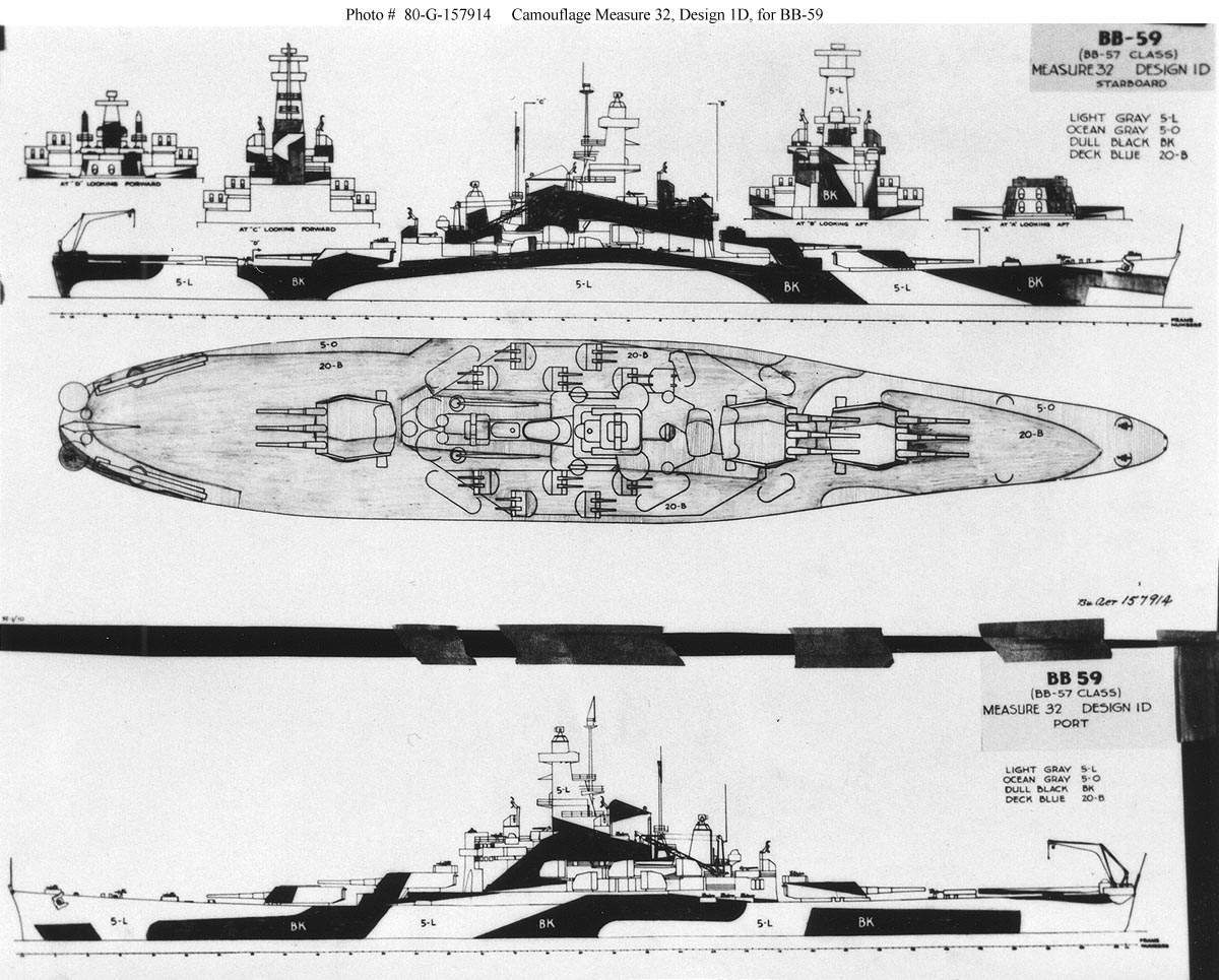 | 170k | Drawing prepared by the Bureau of Ships for Camouflage Measure 32, Design 1D intended for the battleship Massachusetts (BB-59), circa 1943. This camouflage design was not actually used on Massachusetts or any other ship of her class. | Official USN photo # 80-G-157914, from the Bureau of Ships Collection in the U.S. National Archives. | |
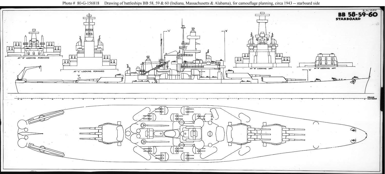 | 129k | Drawing prepared by the Bureau of Ships for use in preparing camouflage designs for the Indiana (BB-58); Massachusetts (BB-59); and Alabama (BB-60), circa 1943. This plan shows the ship's starboard side, superstructure ends and exposed decks. | Official USN photo # 80-G-156818, from the Bureau of Ships Collection in the U.S. National Archives. | |
 | 60k | Drawing prepared by the Bureau of Ships for use in preparing camouflage designs for the Indiana (BB-58); Massachusetts (BB-59); and Alabama (BB-60), circa 1943. This plan shows the ship's port side. | Official USN photo # 80-G-156819, from the Bureau of Ships Collection in the U.S. National Archives. | |
 | 282k | Invasion of North Africa, November 1942. Anti-aircraft fire chases four French fighters away from an American spotting plane, during the early morning hours of the Battle of Casablanca, 8 November 1942. Photographed from the after deck of Massachusetts (BB-59). | USN photo # 80-G-38832 courtesy of Tracy White @ Researcher @ Large. | |
| March 1943 - December 1945 / War in the Pacific |
||||
 | 742k | Inching through the Panama Canal. After a cease-fire had been arranged with the French, she headed for the United States 12 November 1942, and prepared for Pacific duty. | Text courtesy of DANFS. USN photo courtesy of James E. Hesson, plank-owner of the Massachusetts (BB-59). Photo submitted in his memory by his son, Joe Hesson. |
|
 | 270k | Our first fleet base in far Pacific waters. | USN photo courtesy of James E. Hesson, plank-owner of the Massachusetts (BB-59). Photo submitted in his memory by his son, Joe Hesson. | |
 | 348k | Turret two's goblin. | USN photo courtesy of James E. Hesson, plank-owner of the Massachusetts (BB-59). Photo submitted in his memory by his son, Joe Hesson. | |
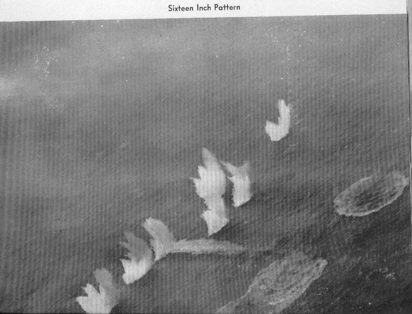 | 340k | Sixteen inch pattern. | USN photo courtesy of James E. Hesson, plank-owner of the Massachusetts (BB-59). Photo submitted in his memory by his son, Joe Hesson. | |
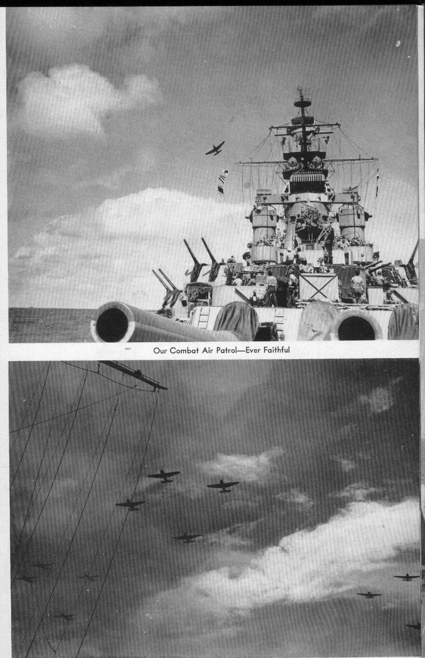 | 760k | Our combat air patrol - ever faithful. | USN photo courtesy of James E. Hesson, plank-owner of the Massachusetts (BB-59). Photo submitted in his memory by his son, Joe Hesson. | |
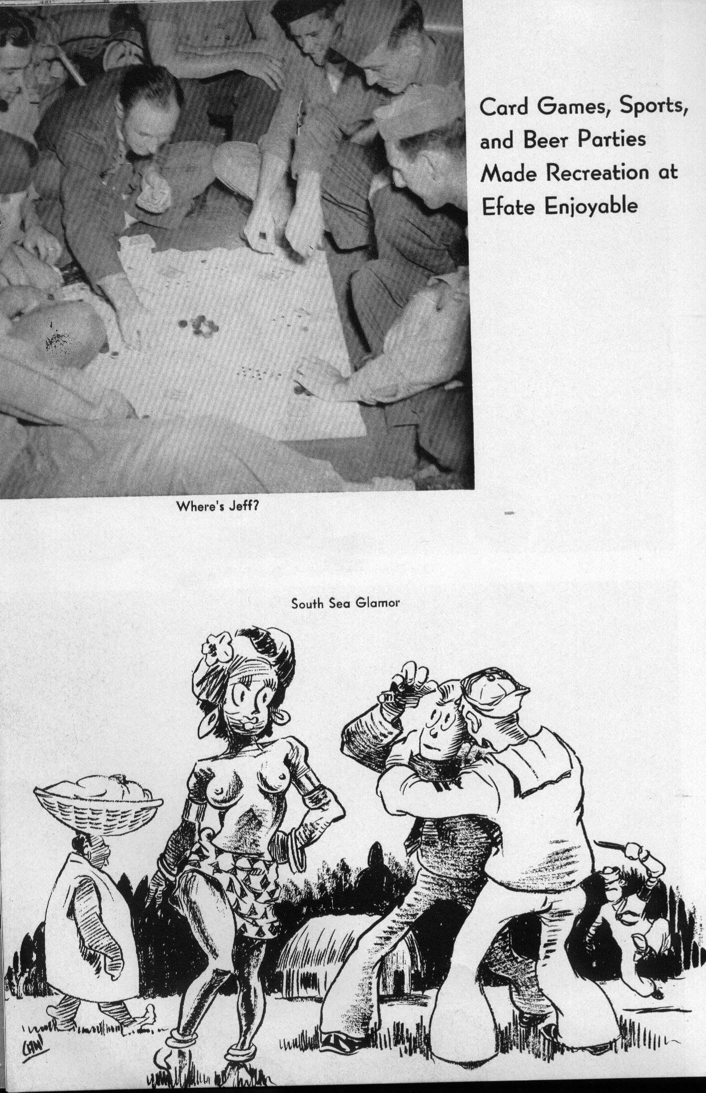 | 544k | Card games, sports, and beer parties made recreation at Efate enjoyable. | USN photo courtesy of James E. Hesson, plank-owner of the Massachusetts (BB-59). Photo submitted in his memory by his son, Joe Hesson. | |
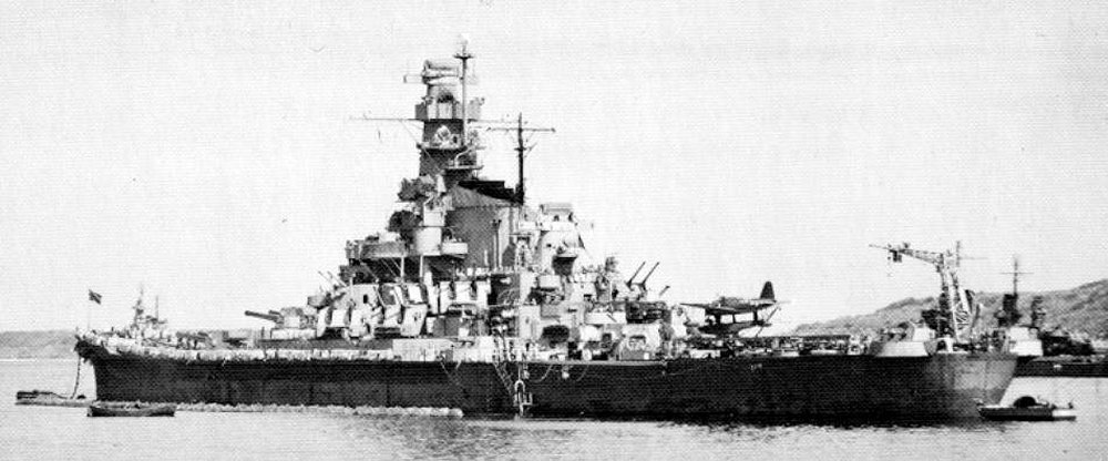 | 45k | Anchored in Efate Harbor. Note the Atlanta class light cruiser in the background. August, 1943. | USN photo. | |
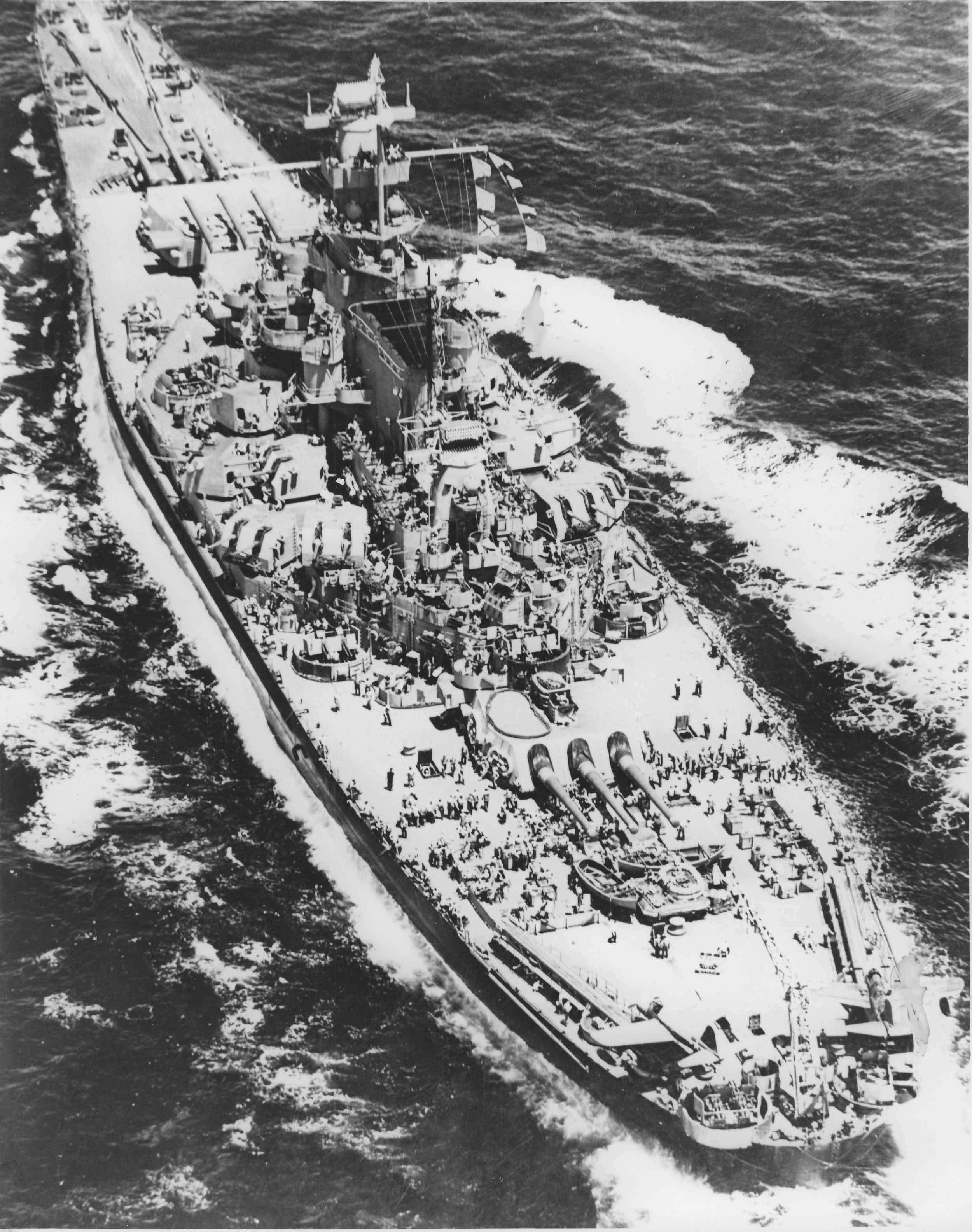 | 638k | Detailed photo showing secondary armament and stern view, 1943. | USN photo courtesy of Pieter Bakels. | |
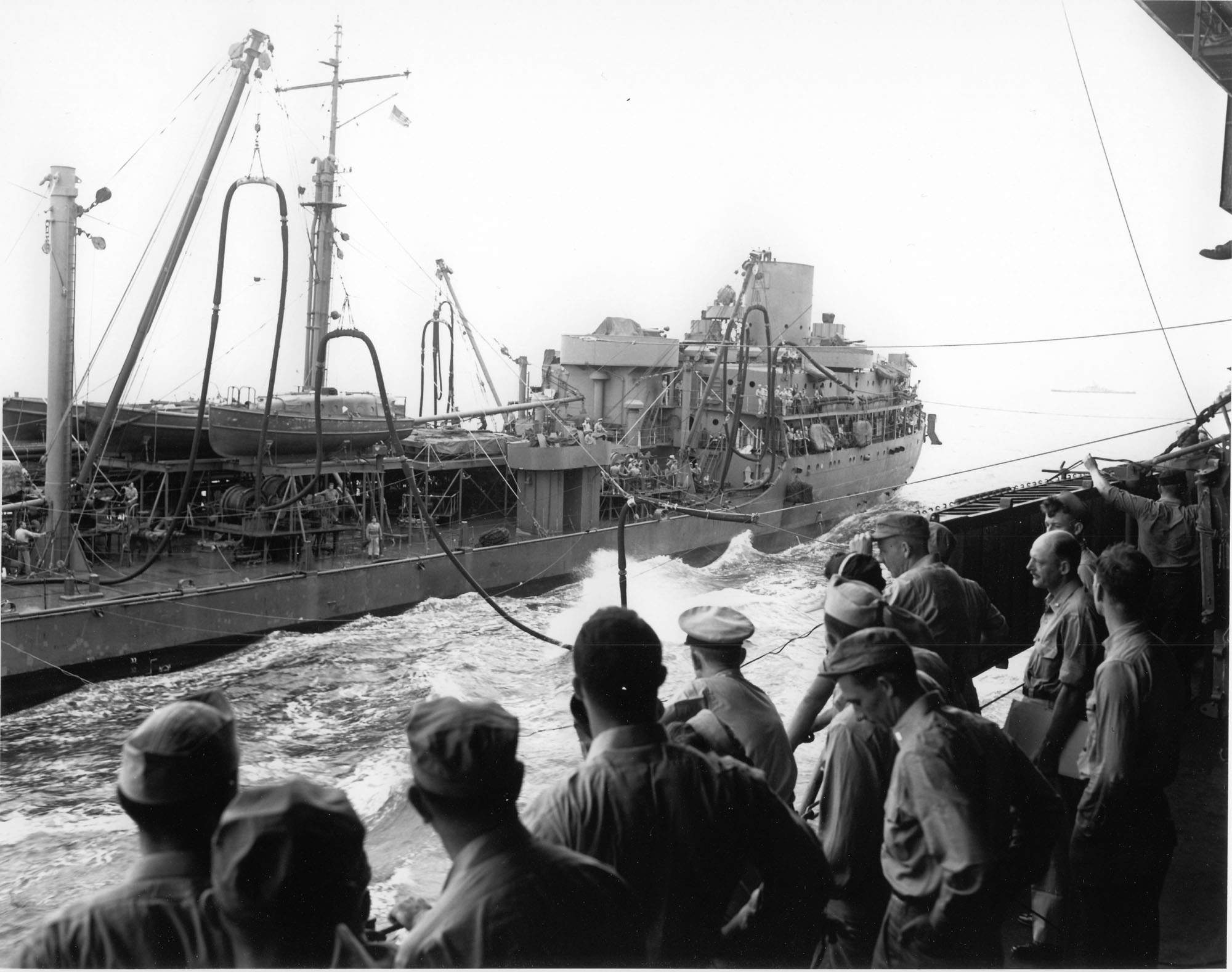 | 262k | Cimarron (AO-22) connects fuel lines to the Massachusetts (BB-59) as Gasoline Officer directs the operation from above on 28 January 1944. | USN photo submitted by Pieter Bakels. | |
 | 706k | Massachusetts (BB-59) shelled Ponape Island 1 May 1944, her last mission before sailing to Puget Sound to overhaul and reline her gun barrels, now well-worn. On 1 August she left Pearl Harbor to resume operations in the Pacific war zone. | Text courtesy of DANFS. USN photo courtesy of James E. Hesson, plank-owner of the Massachusetts (BB-59). Photo submitted in his memory by his son, Joe Hesson. |
|
 | 308k | Massachusetts (BB-59) with heightened mainmast off PSNS after final wartime refit anchored, possibly off the North end of Whidbey Island heading into the Straits. Most probably during her sea trials. | Text i.d. courtesy of Thomas Jacobs. USN photo courtesy of David Buell. |
|
 | 60k | Massachusetts (BB-59) in Washington. This is from a series of photographs of her taken in Puget Sound after her 1944 refit. | Text i.d. courtesy of Mike Getscher, Executive Vice President and COO, Pacific Battleship Center, Battleship IOWA. USN photo courtesy of Mike Green. |
|
 | 2.40k | Broadside view, port side in Puget Sound, 11th July 1944. | Photo # 2174-44 courtesy of Pieter Bakels. | |
 | 40k | At Puget Sound Navy Yard following overhaul, 11th July 1944. | USN photo. | |
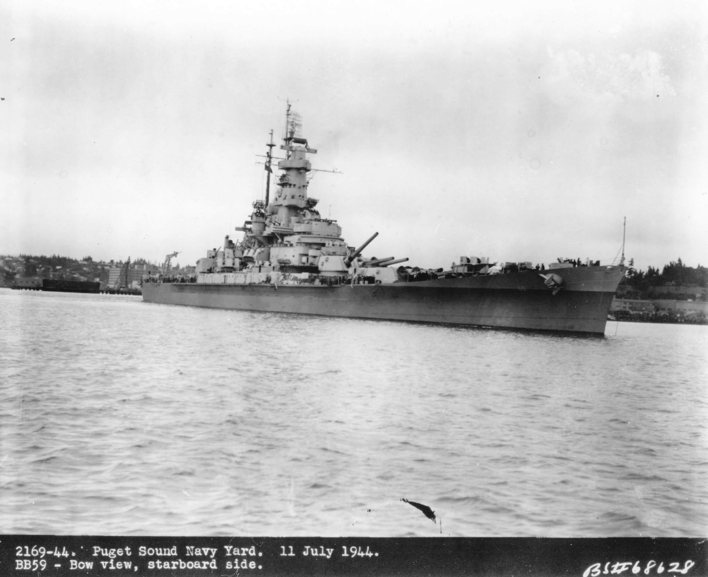 | 232k | At Puget Sound Navy Yard following overhaul, 11th July 1944. | USN photo # 2169-44 courtesy of Pieter Bakels. | |
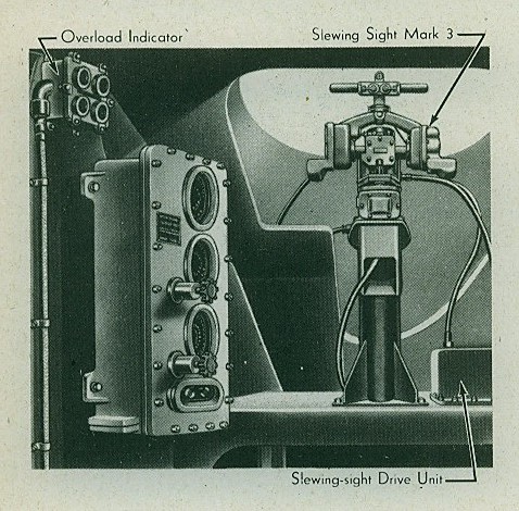
 | 54k | Mk.37 director aboard Massachusetts (BB-59) in October 1944. Please note the Mk.3 slewing sight on the director shield. In this earlier modification three telescopes had been fitted for the trainer, pointer and control officer. The function of the slewing sight was to bring the director telescopes on the rangefinder to bear on a new target in train and elevation in a minimum of time. The equipment was supported at the top of the director shield just forward of the control officer's hatch. The sighting unit mounted on the motor unit projected through an opening in the shield. The motor unit itself was secured within the director shield. After opening the hatch, the operator grasped the handles and slewed the sight bar relative to the director until the bar lined up with target and he closed the "SLEW"switch on the handle. As the introduced train and elevation relative to the director, two potentiometer's movable arms were offset in the motor and caused the train and elevation follow-up motors in the motor unit to be energized. For more information see Directors / General Description and Operation | Photo courtesy of Pieter Bakels. | |
 | 403k | With destroyers off her bow as an escort, a stream of flags flying off her mast and a canvas tarp to provide shelter from the broiling Pacific sun. | USN photo courtesy Pieter Bakels. | |
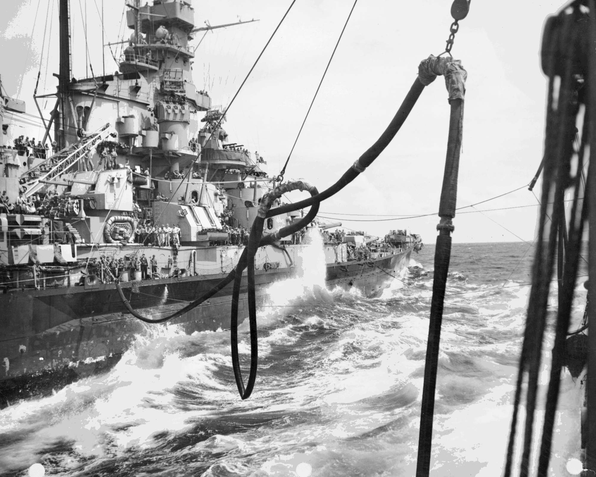 | 316k | Action view showing fueling gear hauled across the water from Kaskaskia (AO-27) to the Massachusetts (BB-59). The hose was suspended from a derrick on the tanker and across on lines passed between the two vessels. It was looped to prevent it dragging in the water. At center right another hose is ready to be passed. The turbulance of the water was caused by the ships operating closely together which made precise stationkeeping essential. Note the battleship's starboard battery of 5 inch/38 guns with one of the controlling mark 37 director above, surmounted by the antenna of a Mk.12 fire control radar. | USN photograph & text courtesy of Pieter Bakels. | |
 | 674k | Massachusetts (BB-59) refueling from the T3-S2-A1 class Kaskaskia (AO-27) during a storm at sea,17 October 1944. Note radar equipment Mk.8 atop Spot 2. | USN photograph courtesy of Pieter Bakels. | |
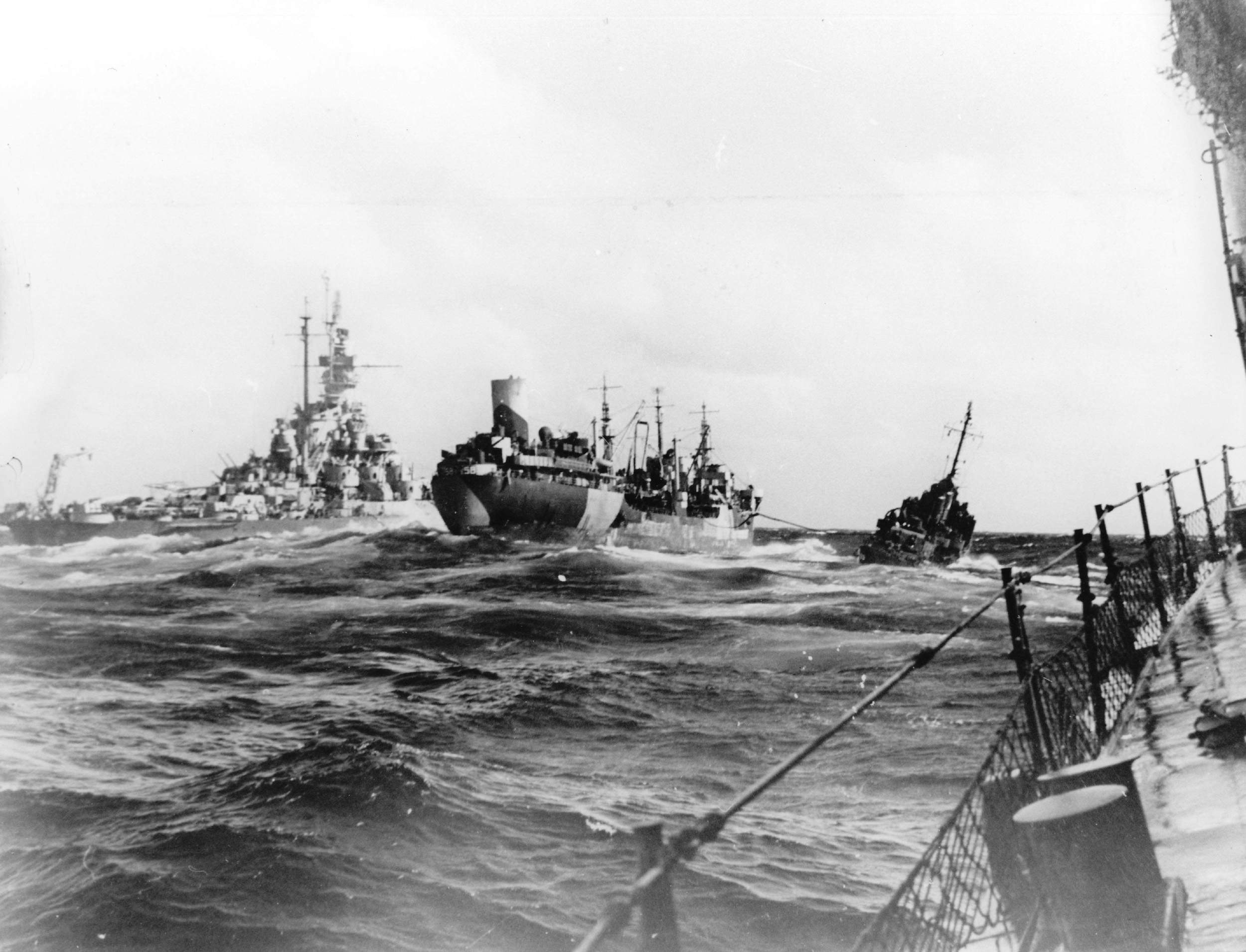 | 350k | Massachusetts (BB-59) refueling from the T3-S2-A1 class Kaskaskia (AO-27) during a storm at sea, 17 October 1944. | USN photograph courtesy of Pieter Bakels. | |
 | 68k | Photo taken from the Massachusetts (BB-59) showing the destroyers escorting her in October 1944. The destroyer on the lower right is the Thatcher (DD-514). The cruiser leading the pack is the Houston (CL-81). | Terry Sanders. | |
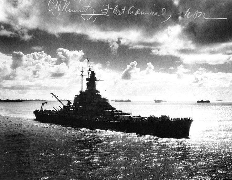 | 85k | Coming into Ulithi Anchorage on 24 November 1944, during a break in operations off the Philippines. Photographed from Wasp (CV-18). Fleet Admiral Chester W. Nimitz has autographed the original print. | Naval History and Heritage Command # NH 58573 from the collections of the Naval Historical Center. | |
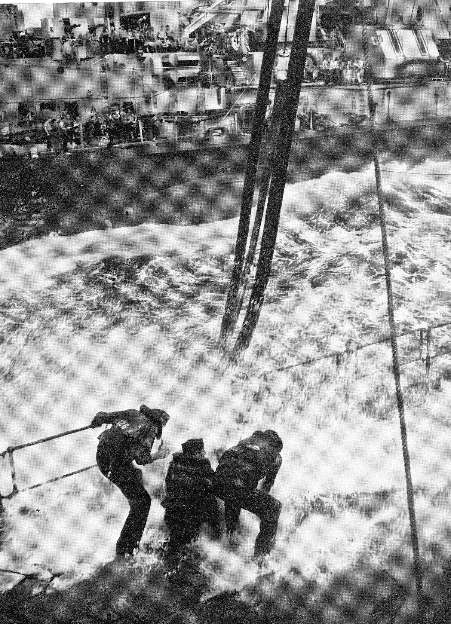 | 1.00k | Salt-water bath-seamen on a tanker take a dousing as they connect up to fuel lines preparatory to fueling the battleship Massachusetts (BB-59) at sea. | USN / USNI photo courtesy of Pieter Bakels. | |
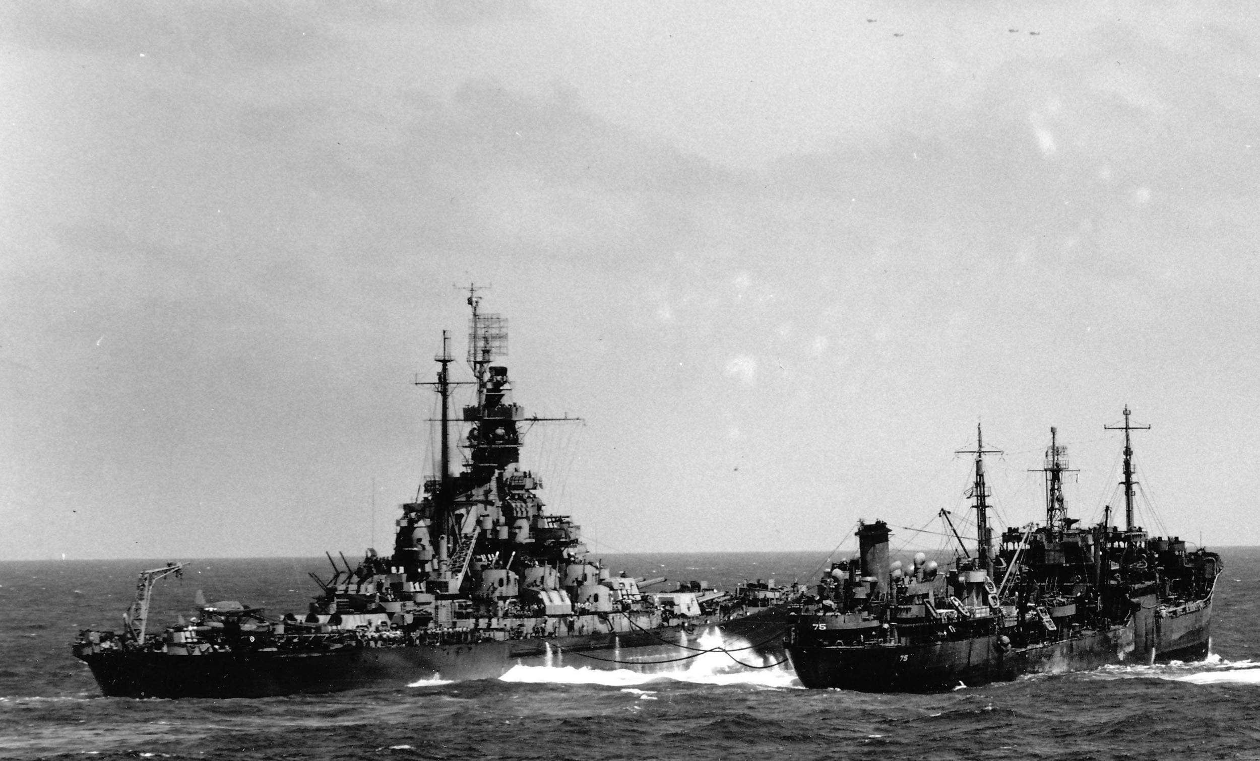 | 380k | Massachusetts (BB-59) refueling from the Saugatuck (AO-75) on 20 April 1945, taken by a photographer on board the Hornet (CV-12). Note the 4 airplanes overhead. | USN photo courtesy of Pieter Bakels. | |
 |
343k | Oil on canvas painting by the artist Wayne Scarpaci entitled Fueling At Sea, 1944 showing the Massachusetts (BB-59) refueling from the Saugatuck (AO-75). | Drawing courtesy of artbywayne.com | |
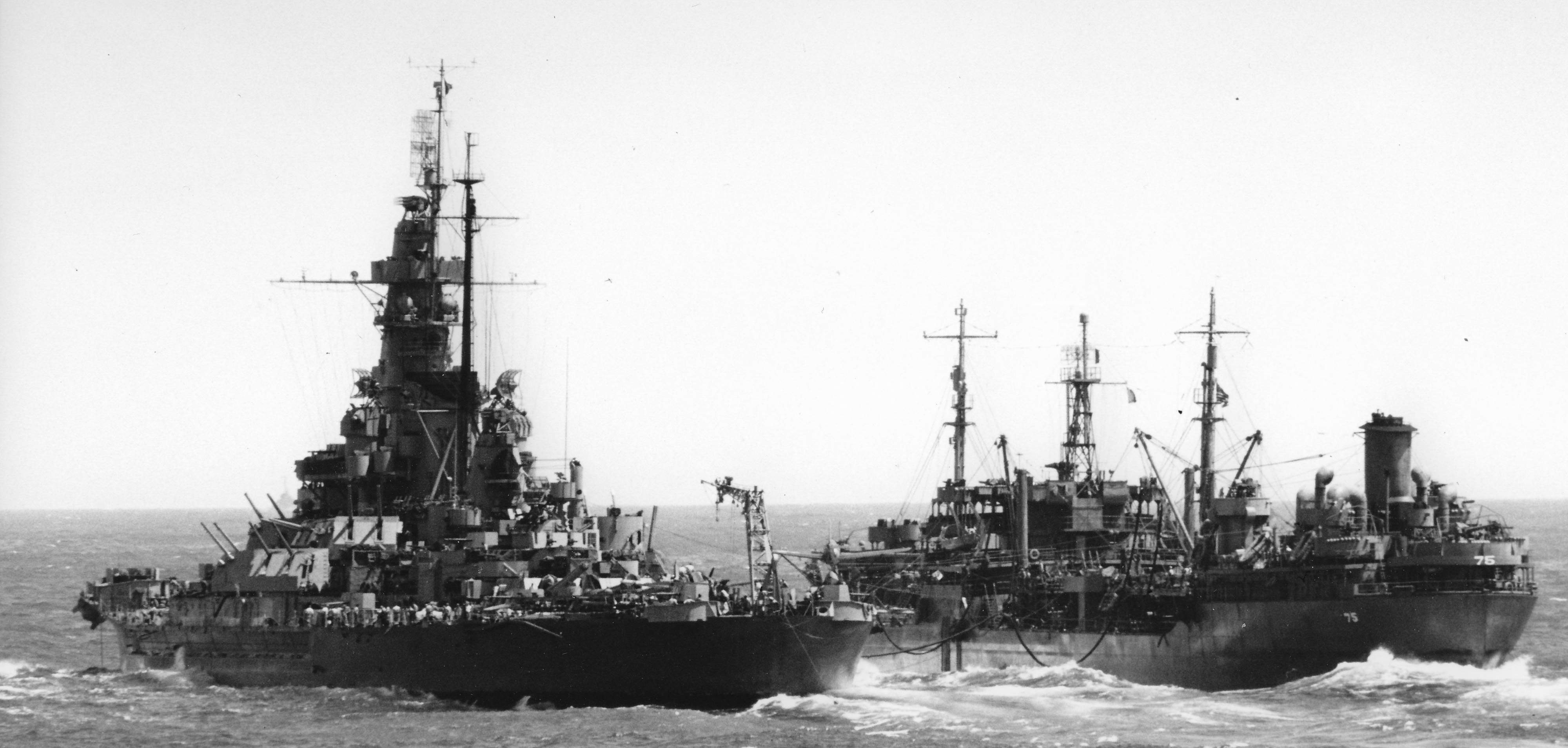 |
468k | Massachusetts (BB-59) refueling from the Saugatuck (AO-75) on 20 April 1945, taken by the Hornet (CV-12). The importance of fleet oilers to the success of U.S. naval operations in WWII is unquestionable. They were the most valuable auxiliaries in the Navy, especially in the Pacific, where their presence facilitated the wide-ranging carriers operations and amphibious assaults conducted thousands of miles from the nearest naval base. Probably no other surface ship contributed so much to the successful conclusion of the war with Japan. During one three-week period in April 1945, Task Force 58, then engaged in operations preceding the invasion of Okinawa, required the services of no less than thirty fleet oilers to provide refueling at sea. The fuel required for the Okinawa operation far exceeded that consumed during any previous campaign with total deliveries to the carrier task force averaging 385,000 gallons of gasoline daily. | USN photo & text courtesy of Pieter Bakels. | |
 |
269k | The United States battleships Indiana (BB-58), Massachusetts (BB-59) and Alabama (BB-60) form a line ahead during target practice as seen from the South Dakota (BB-57), 1945. | USN photo courtesy of Pieter Bakels. | |
 | 320k | Massachusetts (BB-59) replenishing from the Wrangell (AE-12). Wrangell then retired to San Pedro Bay, Leyte, in the Philippines, for upkeep and repairs. Wrangell subsequently returned to the open sea on 8 July and rendezvoused with TG 30.8 (the re-designated TG 50.8) on the 17th. From 20 July to 1 August, she rearmed 35 ships and hit a high point of transferring 700 tons of ammunition in a single day. | USN photo courtesy of Pieter Bakels. Text courtesy of DANFS. |
|
 |
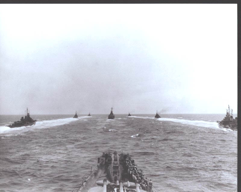
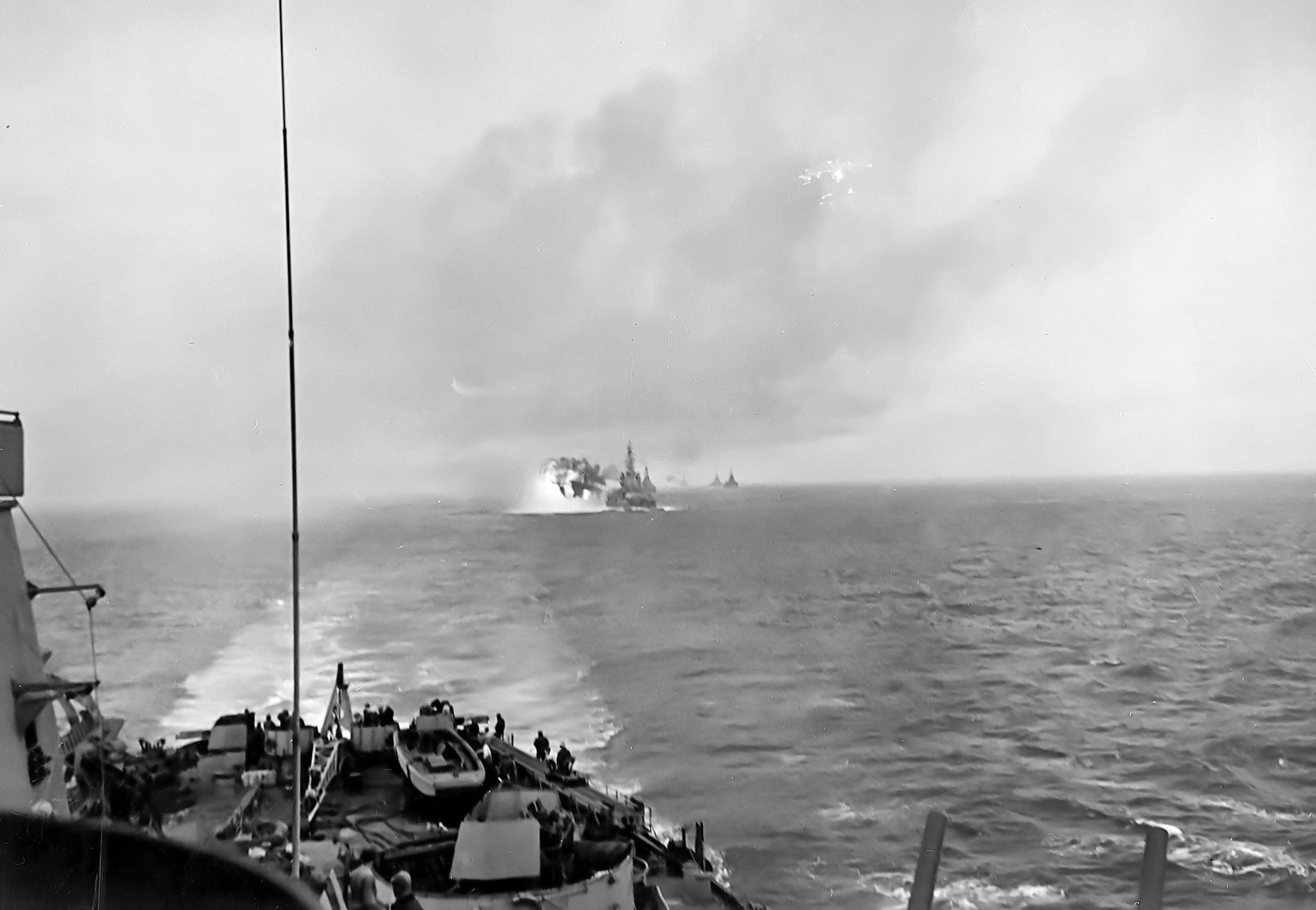
3.22k | THIRD FLEET WARSHIPS FORM BATTLE LINE OFF JAPAN. MOVING IN COLUMN, SOME OF THE THIRD FLEET WARSHIPS MANEUVER NEAR KAMAISHI, ON JAPAN'S HOME ISLAND OF HONSHU ON JULY 14. A FEW MINUTES LATER THEY OPENEDFIRE ON THE IMPERIAL IRON WORKS AT KAMAISHI. NAVY DID NOT NAME WARSHIPS BUT SAID MASSACHUSETTS (BB-59), SOUTH DAKOTA (BB-57), INDIANA (BB-58), QUINCY (CA-71) AND CHICAGO (CA-136) PARTICIPATED IN THE SHELLING. Bombardment of Kamaishi, Japan, 14 July 1945. Battleships and heavy cruisers steam in column off Kamaishi, at the time they bombarded the iron works there, as seen from South Dakota (BB-57). Indiana (BB-58) is the nearest ship, followed by Massachusetts (BB-59). Cruisers Chicago (CA-136) and Quincy (CA-71) bring up the rear. |
API photo, & text courtesy of Pieter Bakels. Text courtesy of Naval History and Heritage Command # NH 80-G-490143. |
|
 015960 | 662k | This image is of Massachusetts (BB-59) as she withdraws from the bombardment of Kamaishi on the northeast coast of Honshu on 14 July 1945. This was part of the first US ship bombardment of the main Japanese home islands. | Photo via Yu Chu & Battleship Cove. | |
 | 828k | Bombardment of Kamaishi Japan, August 1945. Massachusetts (BB-59) opens fire on Kamaishi, in the last battleship bombardment of World War II, 9 August 1945. Photographed from Indiana (BB-58). | Official USN photo # 80-G-339333, now in the collections of the National Archives. | |
 |
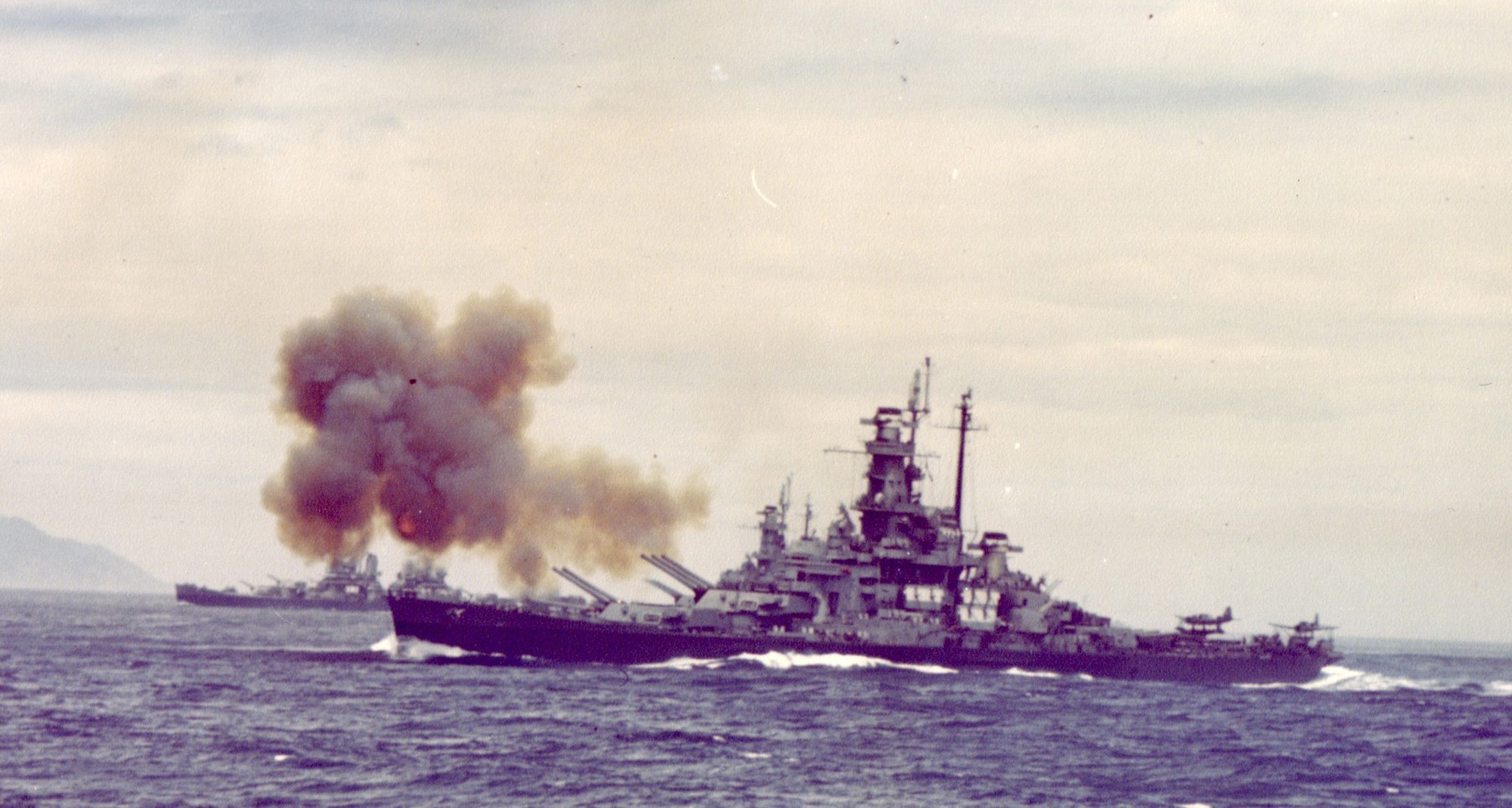
419k | The battleships Indiana (BB-58) and Massachusetts (BB-59) operating off Honshu. The Massachusetts is firing. The South Dakota (BB-57) can be seen behind her. | USN photo courtesy of Pieter Bakels. | |
 |
837k | The Indiana (BB-58) and Massachusetts (BB-59) and two Baltimore Class heavy cruisers close in for a bombardment. | USN photo courtesy of Pieter Bakels. | |
 |
357k | Indiana (BB-58) fires a salvo from her forward 16"/45 guns at the Kamaishi plant of the Japan Iron Company, 250 miles north of Tokyo. A second before, South Dakota (BB-57), from which this photograph was taken, fired the initial salvo of the first naval gunfire bombardment of the Japanese Home Islands. The superstructure of Massachusetts (BB-59) is visible directly behind Indiana. The heavy cruiser in the left center distance is either Quincy (CA-71) or Chicago (CA-136). | Text courtesy of Naval History and Heritage Command from photo # 80-G-K-6035. PDF & photo courtesy of Pieter Bakels. | |
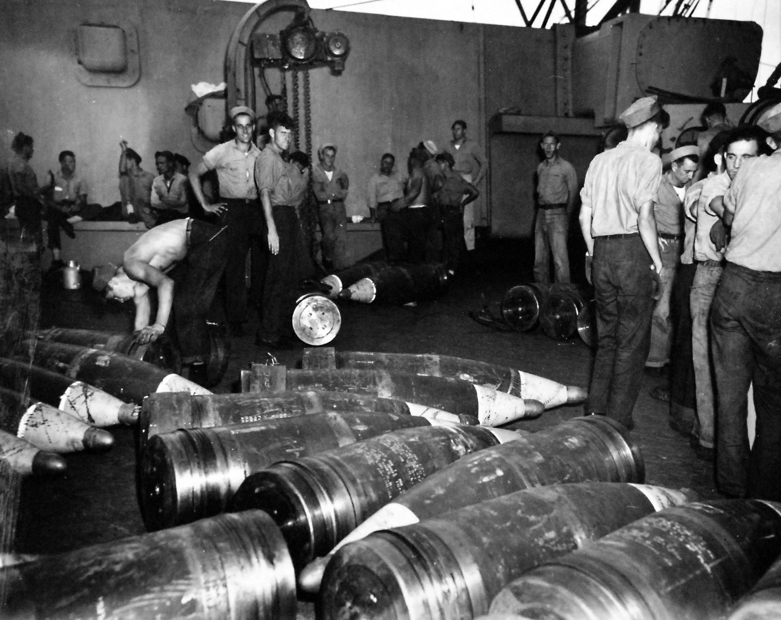 | 503k | Shells piled on deck of Massachusetts (BB-59) waiting to be stored. Photograph by PhoM G.M. Bain, 12 September 1945. | USN photo # 80-G-339312, courtesy of the National Museum of the U.S. Navy, via flickr.com. | |
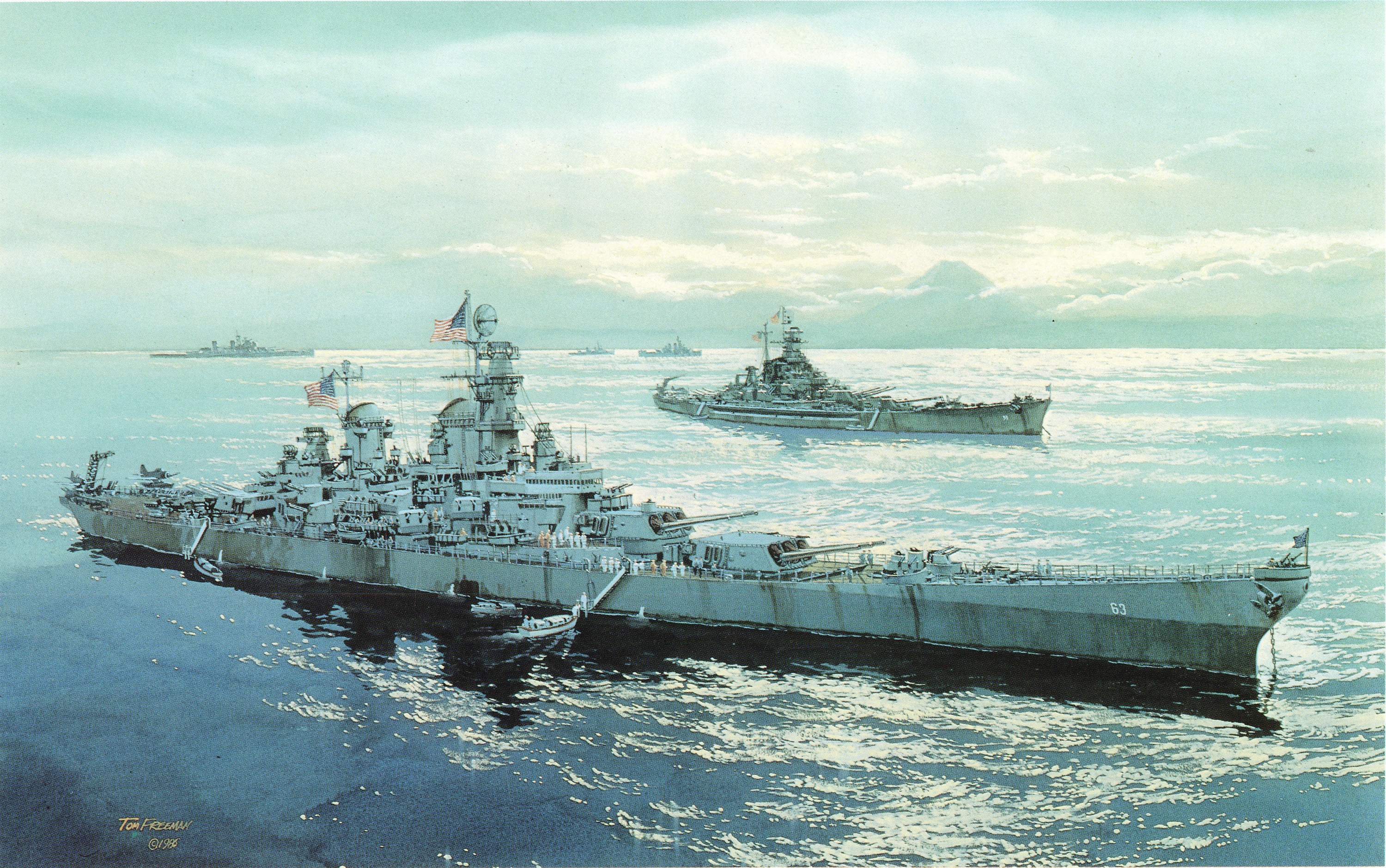 |
1.30k | Watercolor of Missouri (BB-63) & Massachusetts (BB-59) & other units of the Pacific Fleet at war's end by Tom Freeman. | Photograph courtesy of Pieter Bakels. | |
 015927 | NR | B'NAI B'RITH FIRST CIVILIAN ORGANIZATION TO GET WAR SERVICE CITATION FROM NAVY DEPARTMENT) (ABOVE) Text of the Navy Department's citation to B'nai B'rith in recognition of its outstanding war time service on behalf of the U. S. Navy. The citation reads: "Inrecognition of exceptional accomplishment in behalf of the U. S. Navy and of meritorious contribution to the national war effort." (BELOW) Navy honors B'nai B'rith for war-time service—Rear Admiral Forrest P. Sherman, former chief of staff to Admiral Nimitz, acting as the official representative of the Navy, presents Navy citation to Henry Monsky, president of B'nai B'rith. Looking on are Ben G. Shapiro, president of Boston's Amos Lodge, which originated B'nai B'rith serve-a-ship program in 1942, and Lt. Col. Elliot Niles, a member of B'nai B'rith's National Postwar Service-Americanism Commission, who inaugurated the serve-a-ship program of which he is chairman, with service to the battleship Massachusetts (BB-59). |
Image and text provided by University of Florida. Photo & text by The Southern Jewish Weekly. [volume] (Jacksonville, Fla.) 1939-1992, 01 December 1945, Image 1, courtesy of chroniclingamerica.loc.gov. |
|
| 1946 - Present |
||||
 | 286k | Stern view showing her license plate, Massachusetts (BB-59), taken either at 1st refit May - July 1944 or 2nd refit, September 1945 to January 1946. | USN photograph courtesy of Pieter Bakels. | |
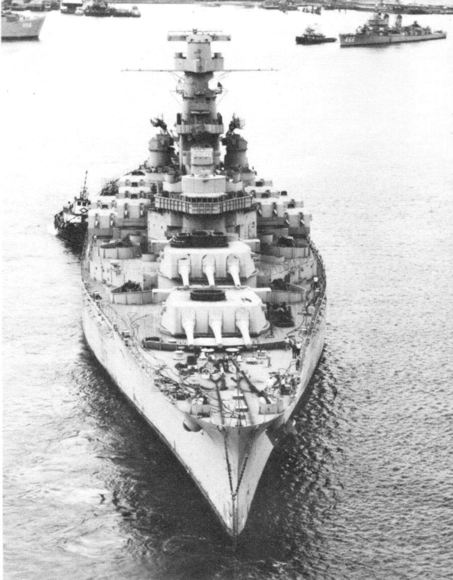
 | 3.50k | Victory won, the fighting battleship sailed for Puget Sound and overhaul 1 September. Bow view of the Massachusetts (BB-59) taken on post refit trials on 22 January 1946. | USN photo courtesy Pieter Bakels. | |
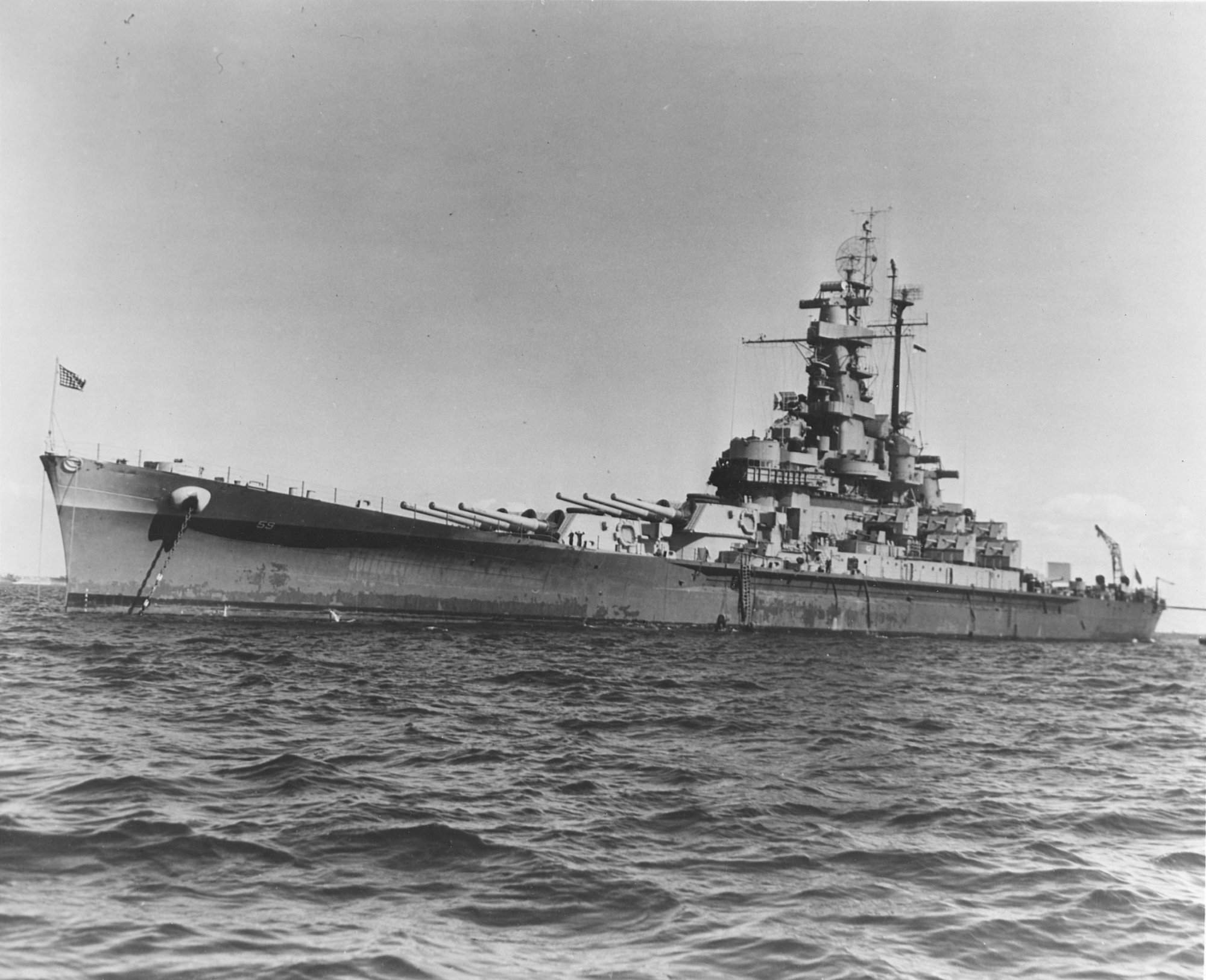
 | 748k | The Massachusetts (BB-59) pictured off Puget Sound 22 January 1946. Broad on port beam at 6 knots. | USN photo courtesy of David Buell. | |
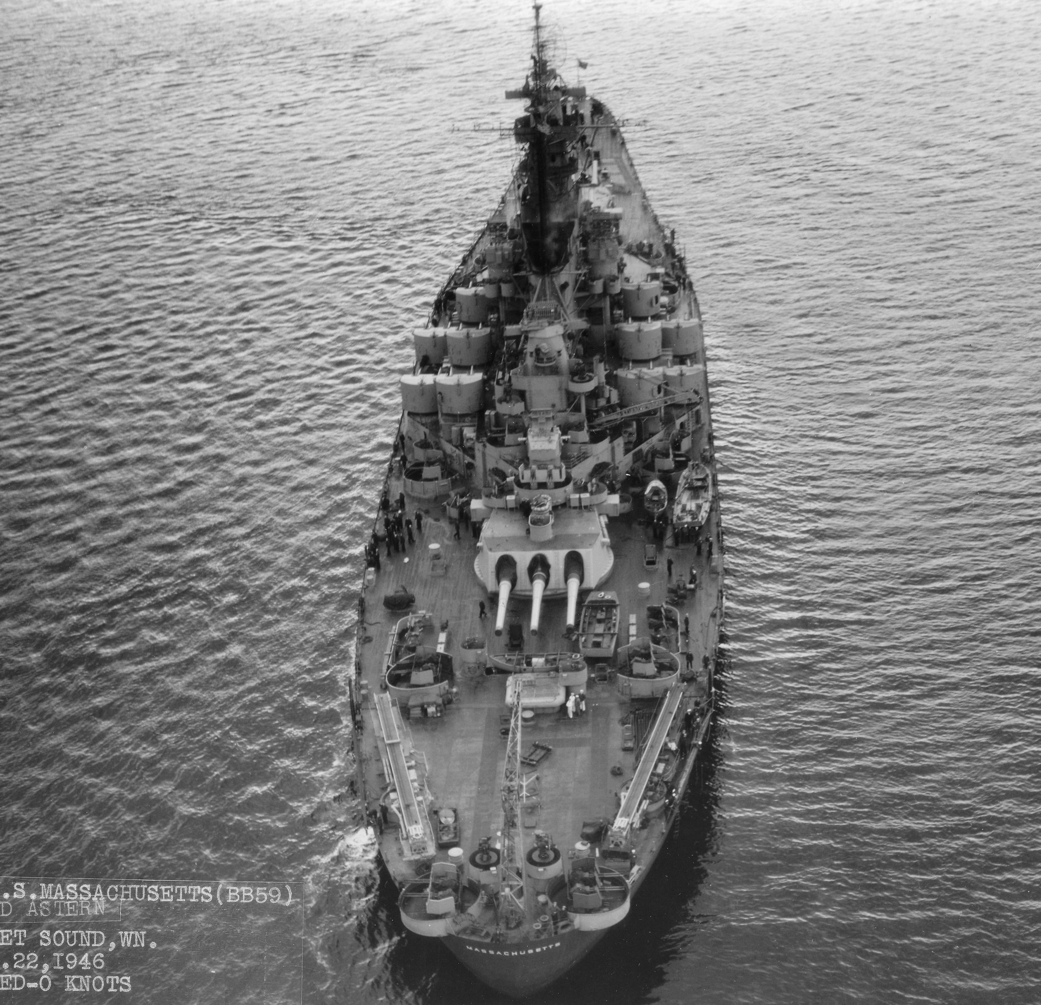 | 1.04k | A few knots of speed show in this stern view of the Massachusetts (BB-59) taken on post refit trials on 22 January 1946. | USN photo courtesy of Pieter Bakels. | |
 | 240k | Broadside view of the Massachusetts (BB-59) in her final active appearance, photo taken on post refit trials on 22 January 1946. 40mm mounts have been removed; these were two "wet" ones ahead of #1 turret and the mount which was atop #2 turret. As well as saving weight and manpower, removing the bow mounts also freed up #1 turret firing, as these mounts obstructed the line of sight of #1 turret, cutting off 15 degrees of training and not allowing firing under 2 degrees of barrel elevation. The bow mounts were added, along with a pair of mounts just ahead of the catapults, as extra A.A. defense was needed. | USN photo courtesy of David Buell. Insert photo courtesy Pieter Bakels. | |
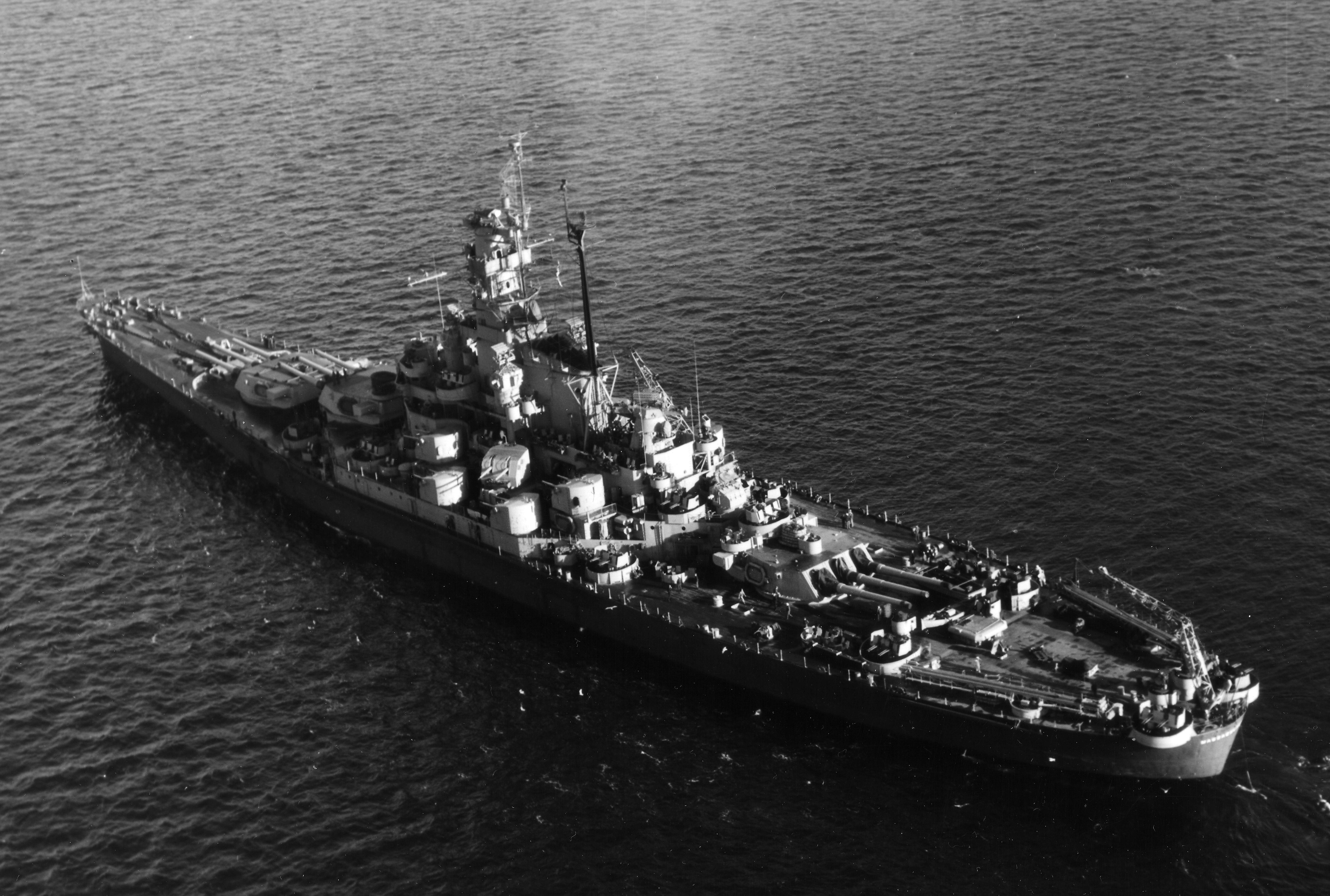 | 1.80k | Port beam view of the Massachusetts (BB-59) taken on post refit trials on 22 January 1946. | USN photo courtesy Pieter Bakels. | |
 | 3.30k | Under way at six knots in Puget Sound, Washington, after her final overhaul, 22 January 1946. | USN photo courtesy of Pieter Bakels. | |
 016043 |
383k | Massachusetts (BB-59) (foreground) and Alabama (BB-60) in San Francisco, early 1946. Notice in bottom left foreground the anemometer cup and windvane on the yardarm of Indiana (BB-58). | Photo courtesy of Battleship Cove via Yu Chu. | |
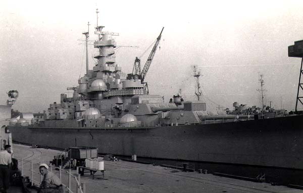
 | 169k | Massachusetts (BB-59) as seen in 1946 at the St. Helen's annex at Berth #1 at Norfolk Naval Shipyard. She is in commission in reserve and is being prepared for decommissioning. St Helena is across the river, where the tanker is sitting at one of the angled piers. The building you see in the left margin is Bldg 74, which is now the IT building. | Text i.d. via Brian Baird. Photo courtesy of Mike Green / Leeward Publications "SHIP'S DATA". |
|
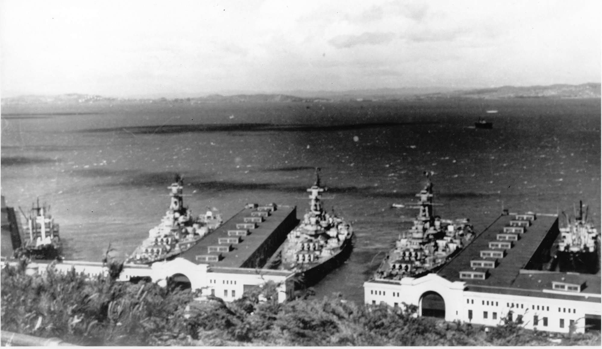 | 158k | 17 March 1946. The Indiana (BB-58), Massachusetts (BB-59) & Alabama (BB-60) tied up at the Embarcadero, San Francisco. | USN photograph courtesy of Pieter Bakels. | |
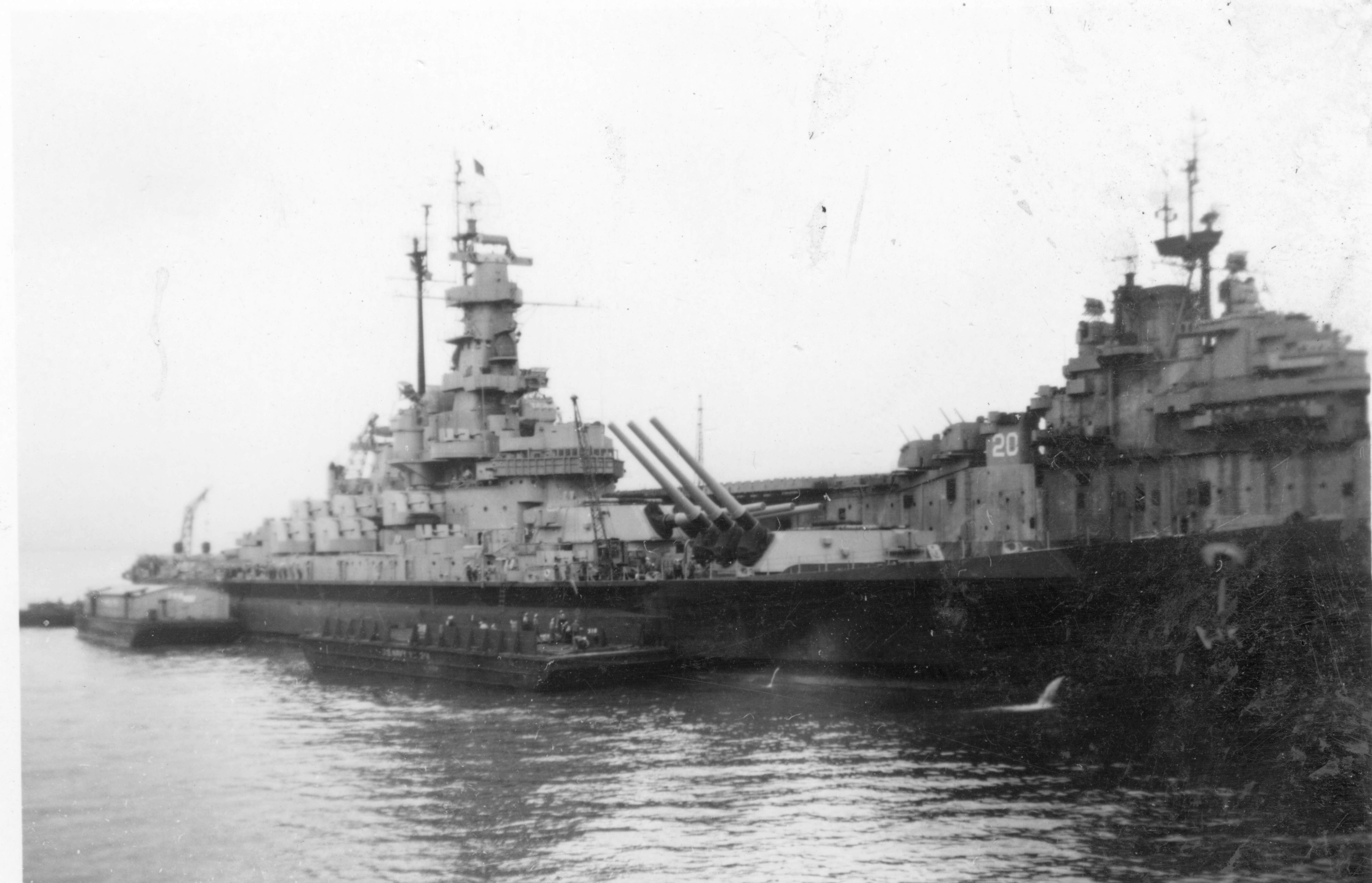 | 1.16k | Massachusetts (BB-59) & Bennington (CV-20), late 1940's. | USN photograph courtesy of Pieter Bakels. | |
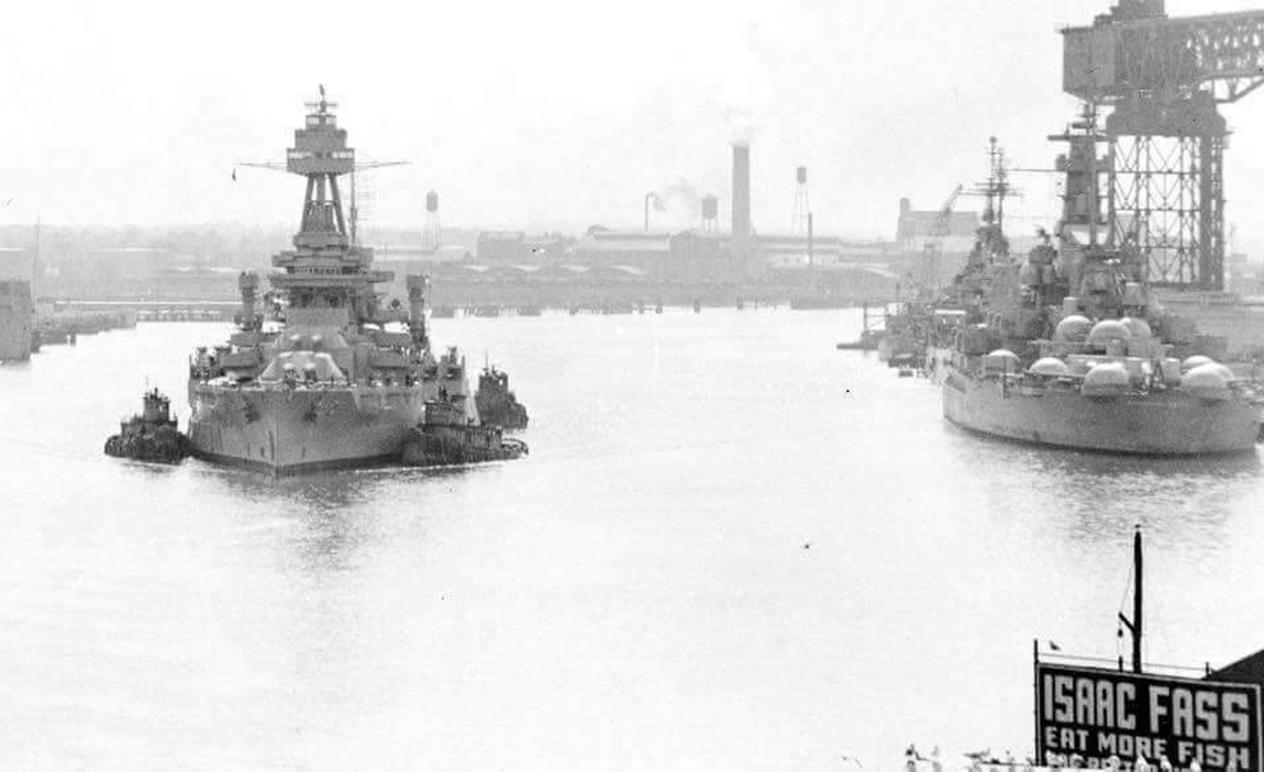 013573b | 280k | The battleship Texas (BB-35) is shown leaving Norfolk Naval Shipyard in March 1948 to begin its journey to the state of Texas, where it was presented as a memorial. Massachusetts (BB-59) sits quietly to her side awaiting her fate that would follow this same journey but back to her home of Massachusetts. | Photo courtesy of USS Massachusetts Museum via Yu Chu. | |
 | 29k | Massachusetts (BB-59) in moth balls at the St. Helena docks (Just across the river from the Norfolk Naval Shipyard,) Portsmouth 6/30/53. | Courtesy of Larry Bohn. | |
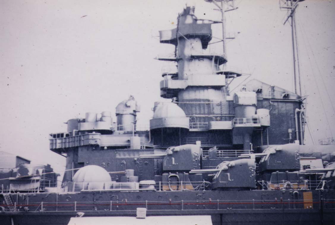 | 69k | View of the Massachusetts (BB-59) bridge area and 5" guns in moth balls at St. Helena, 12/20/54. | Courtesy of Larry Bohn. | |
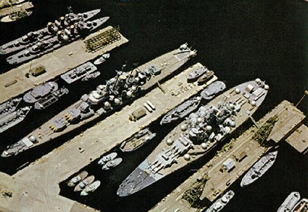 | 213k | Massachusetts (BB-59), cruiser Salem and two unnamed Fletcher class destroyers in the Atlantic Reserve Fleet at the Norfolk Navy Yard, circa 10/7/58 - 6/8/65. The ships are dehumidified as evidenced by the cocoons covering their light weight A.A. weapons. Fuel and supply barges surround the ships as at this time there was still a possibility of the ships being reactivated. As the ships grew older in reserve the possibility of reactivation dimmed and the various ships were grouped together until they were stricken and usually scrapped. Happily for the Massachusetts and Salem, they were saved as memorials to the sacrifices of the armed service personnel. | USN photo. | |
 | 180k | Massachusetts (BB-59) leaving Norfolk Navy Yard under tow. She is heading for a permanent berth at Fall River, Massachusetts. | Courtesy of Mike Green / Leeward Publications "SHIP'S DATA". | |
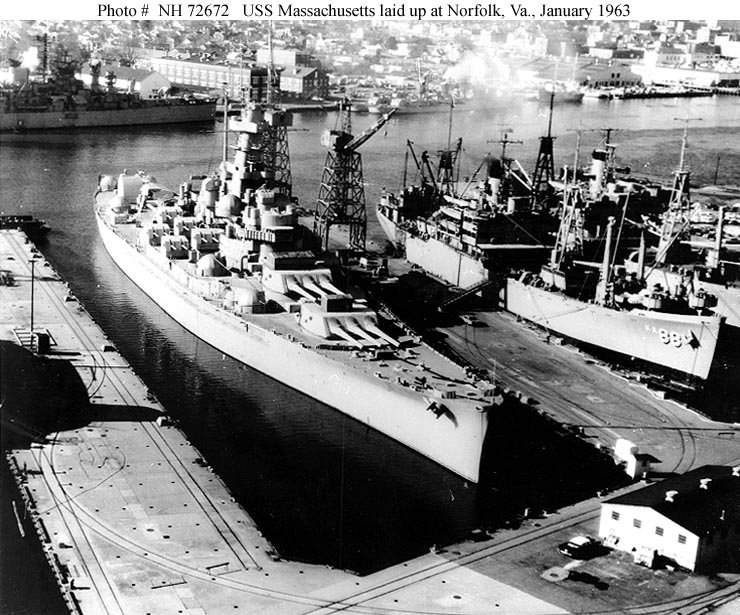 | 86k | Uvalde (APA-88) and Massachusetts (BB-59) laid up at Norfolk, Va. January, 1963. | USN / Naval History and Heritage Command # NH 72672, from the collections of the Naval Historical Center. | |
 | 903k | View of ex-Massachusetts (BB-59) as tugs maneuver it into position beneath a bridge in Fall River, Massachusetts, to its new home as a museum ship, 12 June 1965. | Source: United States National Archives, Photo No. USN 1111700 via Mike Green. | |
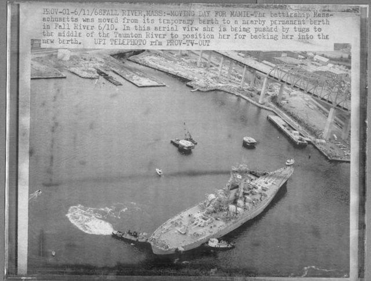 | 692k | Massachusetts (BB-59) on the move in 1968. | Photo courtesy of Tommy Trampp. | |
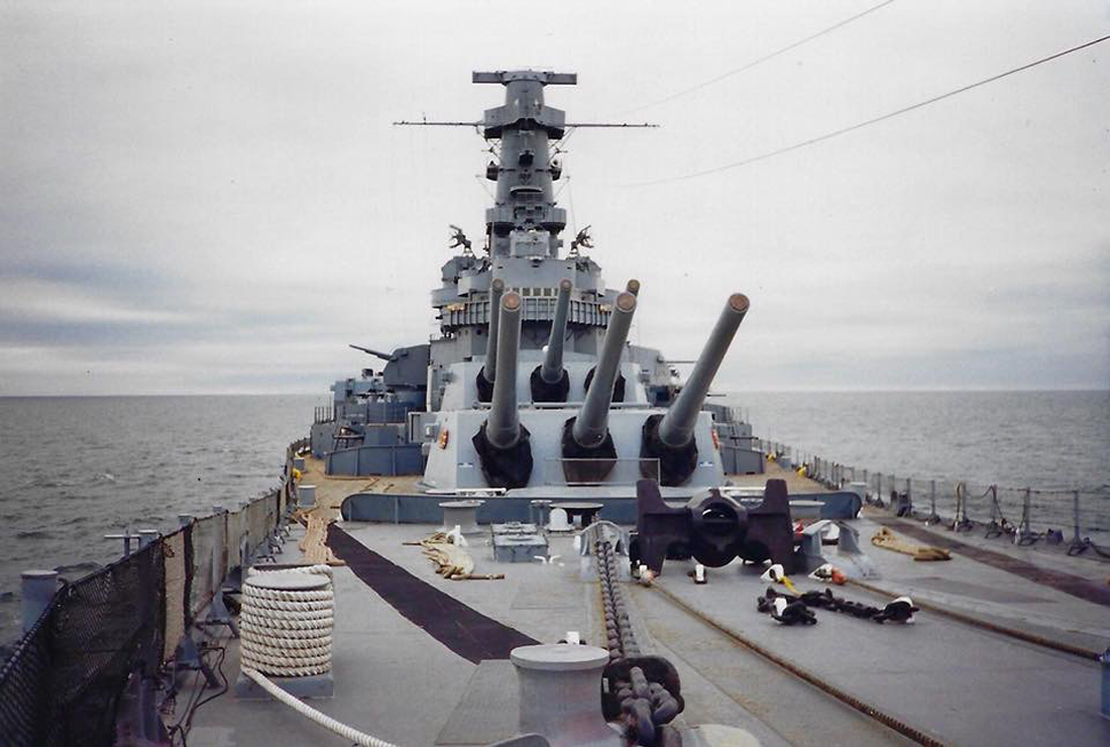
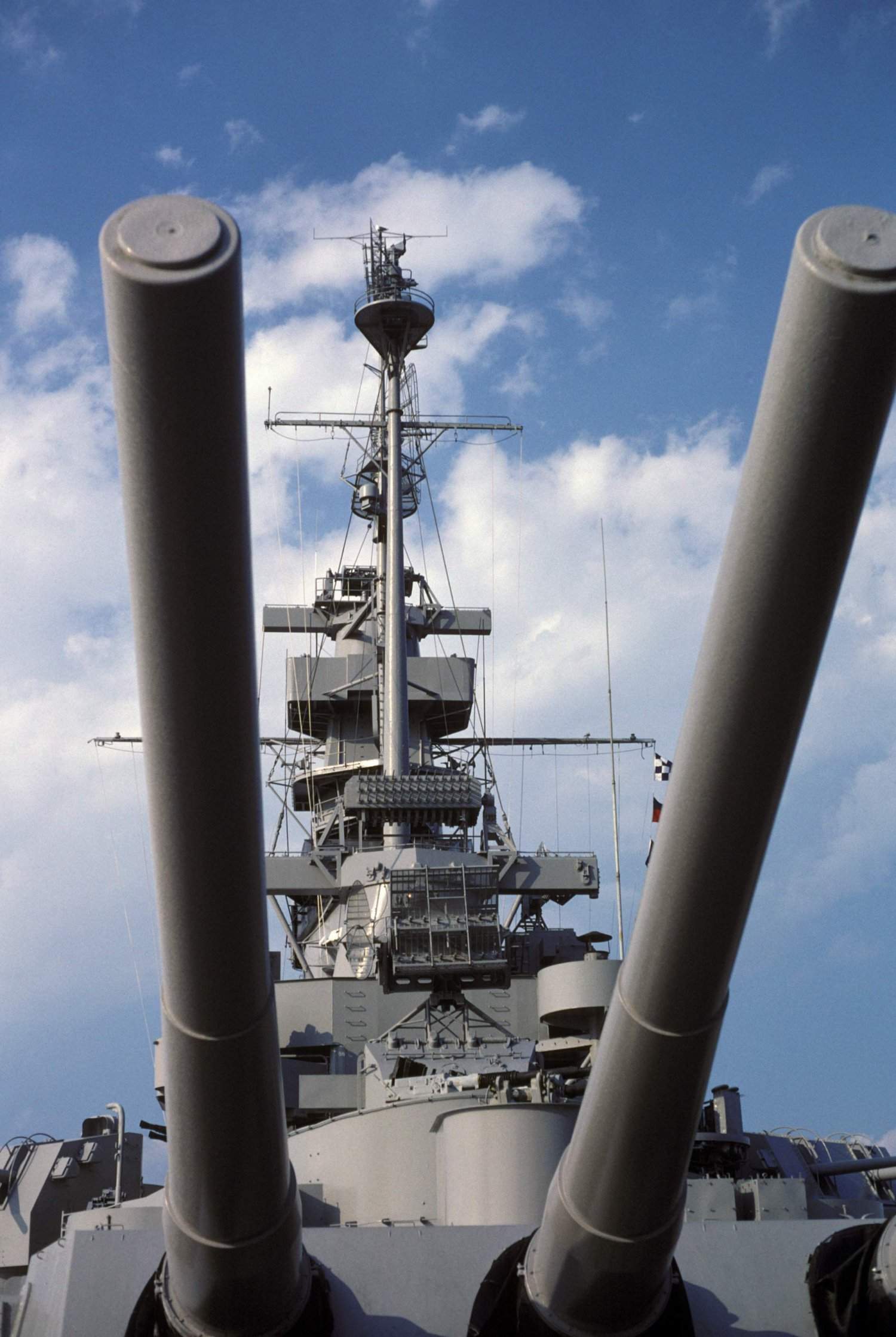 | 221k | A view of the superstructure of the memorial battleship Massachusetts (BB-59) as seen from the ship's stern on 30 May 1987. The No. 3 Mark 6 16-inch/45-caliber guns are in the foreground. | USN photo # DN-ST-87-07706, by Don S. Montgomery, from the Department of Defense Still Media Collection, courtesy of dodmedia.osd.mil. | |
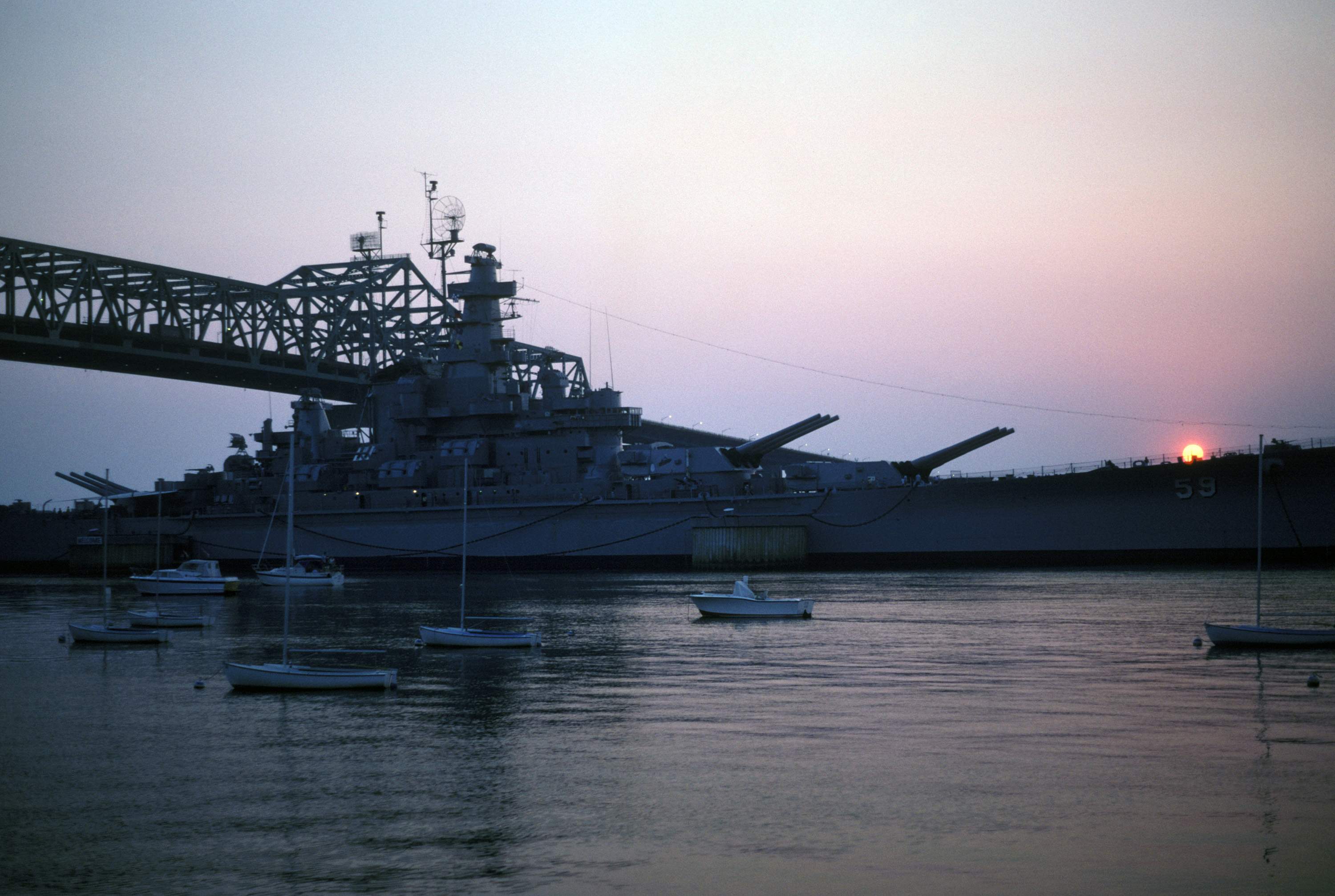 | 480k | A starboard bow view of the memorial battleship Massachusetts (BB-59) at sunset. | USN photo # DN-ST-87-07708, by Don S. Montgomery, from the Department of Defense Still Media Collection, courtesy of dodmedia.osd.mil. | |
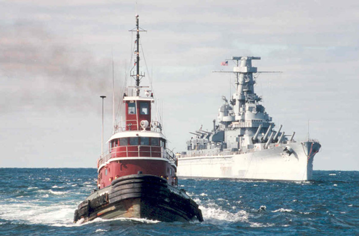
 | 118k | The tug Narragansett helps move the Massachusetts (BB-59) in preparation for towing to Boston in December, 1989. | Photograph courtesy of Pieter Bakels. | |
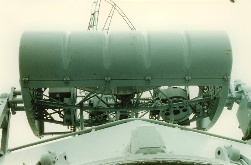
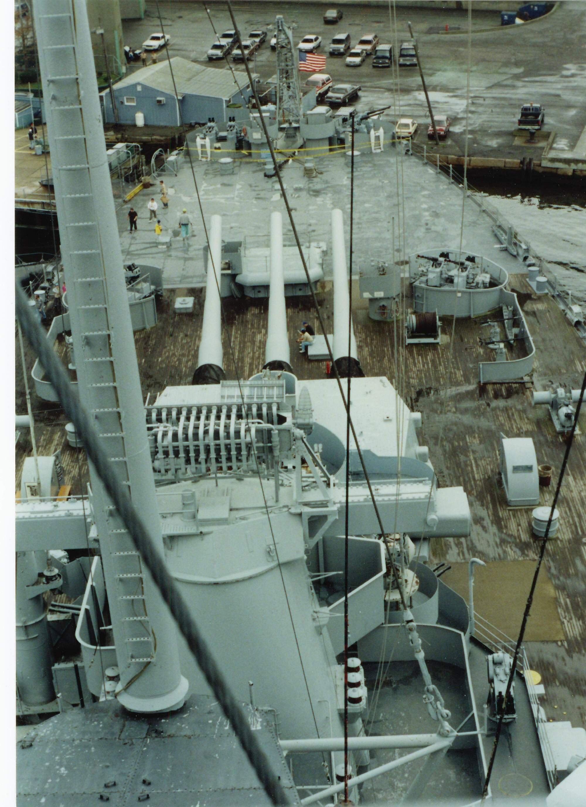 | 487k | Looking aft from Fwd.Air Defense, Spot 2, with Main Battery Fire Control Radar Mk.8 atop, aft of that, #3 16-Inch Turret while at Fall River in 1991. This Image was taken from her Forward Air Defense Level. Note the Mk.8 Main Battery Fire Control Radar atop her Mk.38 Main Battery Fire Control Director (there were two types of this type of director aboard; one at the top of the foremast structure, designated as Main battery director One, and the other located aft of the stack, designated as Main Battery Director two- these directors were armored directors with a crew of six.) and the 40mm Loading Machine to the right. The Mk.8 radar had excellent Range accuracy. Bearing accuracy was practically as good as optics. Spotting in range was excellent- fall of shot within one thousand yards of target range was accurate to the nearest one hundred yards. Spotting in bearing was not practical for small deflection errors. The antenna was stabilized in level from either two sources, the Stable Vertical in Main battery plot or local rangefinder level. Range was transmitted to Main Battery plot electrically, each time the Range Unit Transmitter button was depressed. Generated Range was not at the time (1944-1945) fed back into the Range Unit. All operating and control units of the radar were mounted in the director. Later provision was made to move the greater part of the operating and control units down to Main Battery Plot as first installed experimentally on Washington (BB-56). Operation required one radar operator and the director train operator. | Photograph courtesy of Pieter Bakels. | |
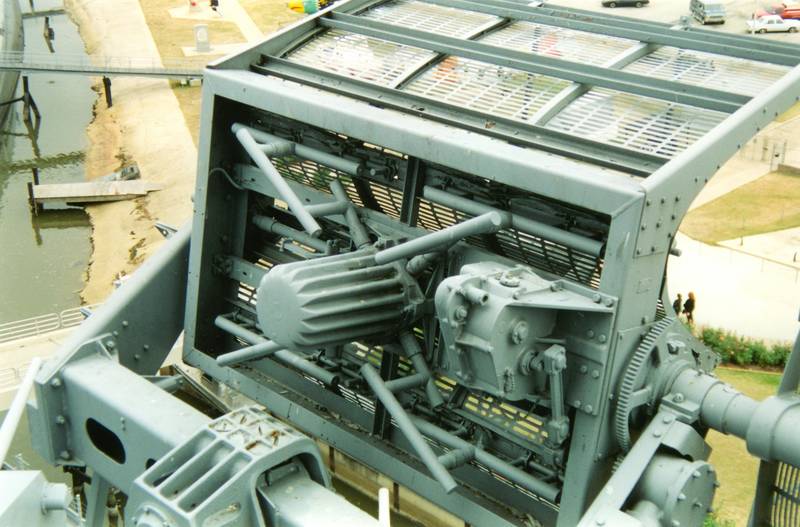
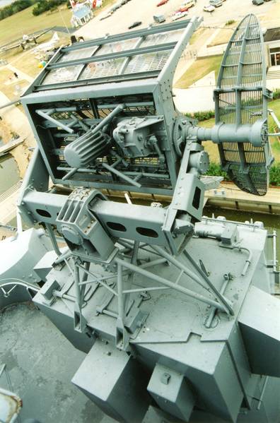
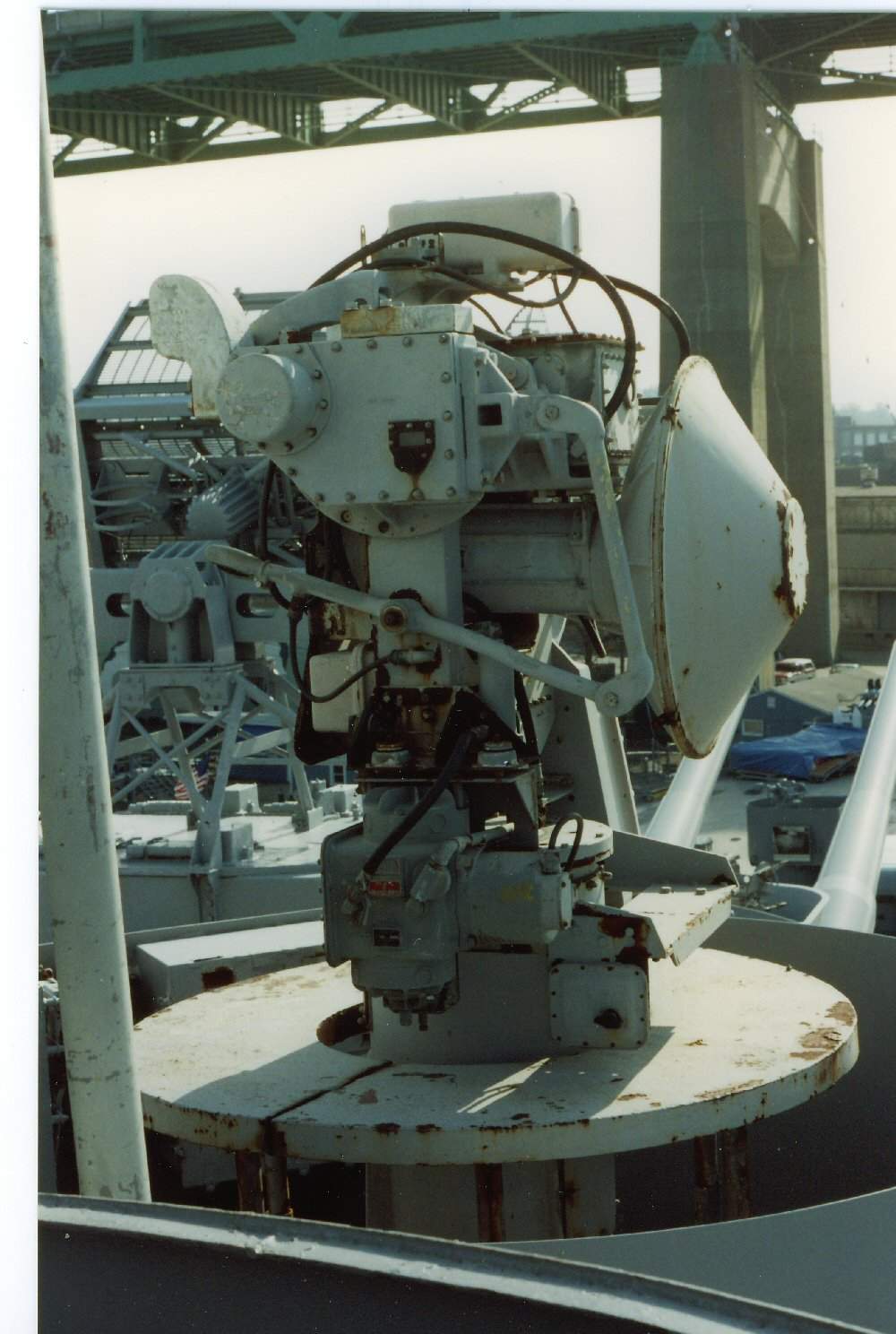 | 125k | GFCS Mk.57 w.Radar Equipment Mk.34, could control the fire of two or three different calibers simply by throwing some switches to compensate for ballistic differences. | Photograph courtesy of Pieter Bakels. | |
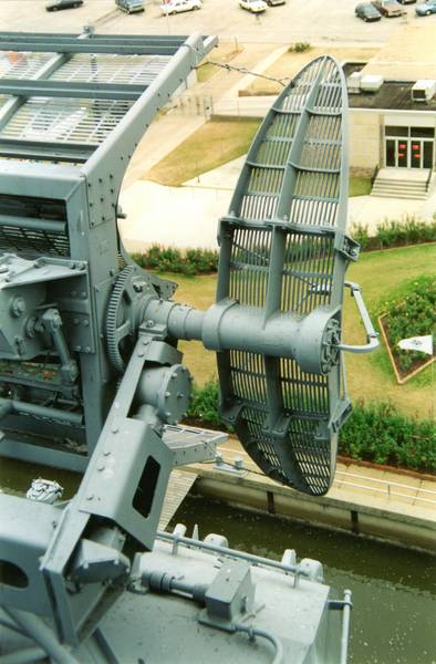
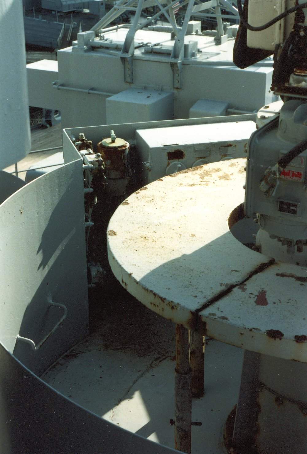 | 128k | Radar Equipment Mk.34 measured Range out to 40,000 yards and permitted observation out to 60,000 yards, provided Range-Rate data and indicated Bearing and Elevation of the Target. | Photograph courtesy of Pieter Bakels. | |
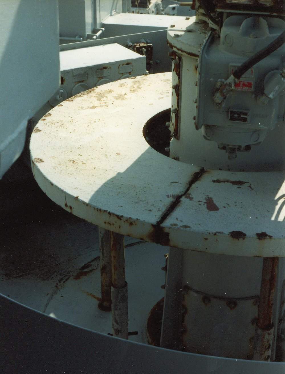
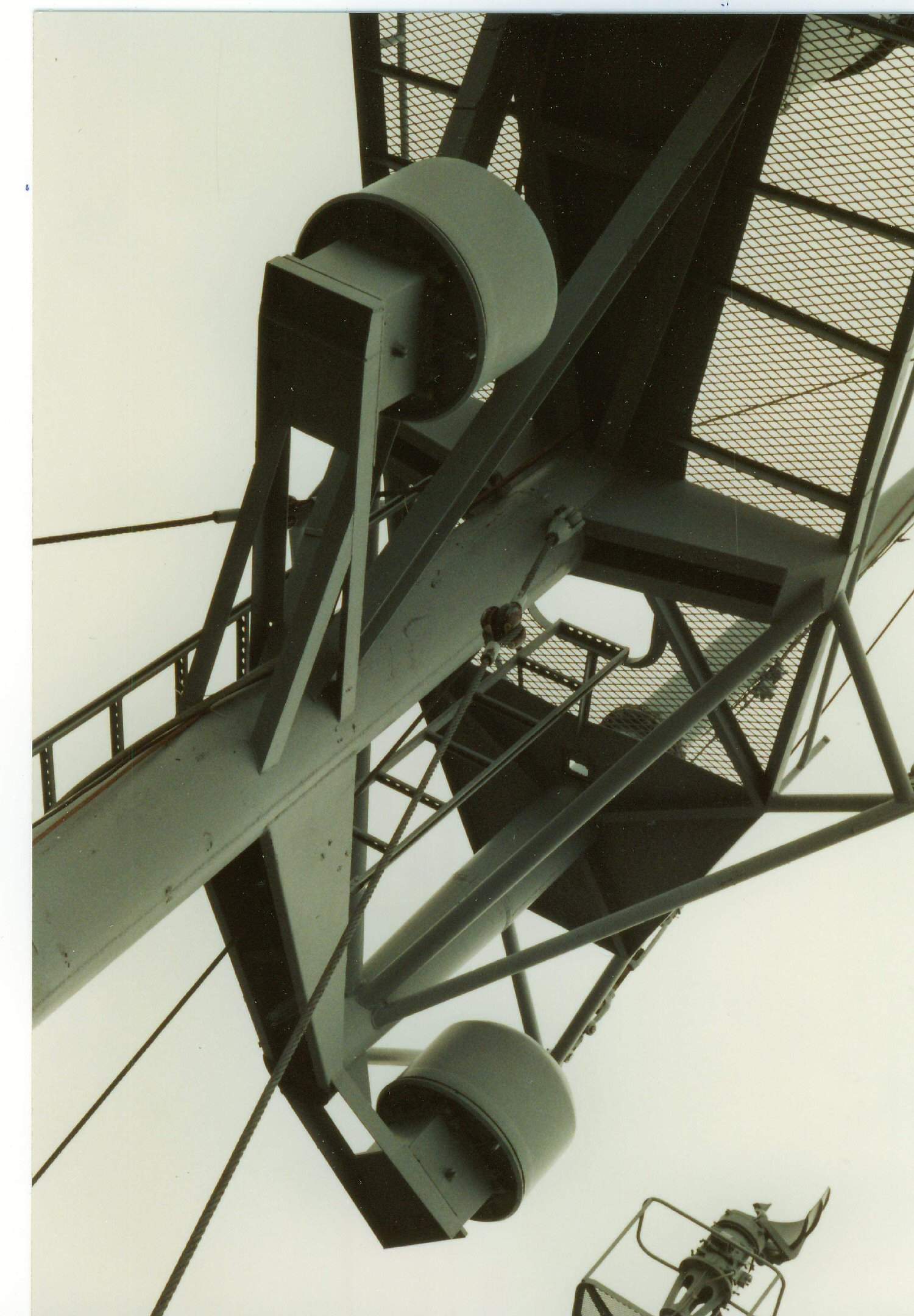 | 249k | DBM antennas aboard Massachusetts (BB-59) in 1991. | Photograph courtesy of Pieter Bakels. | |
 | 32k | On her maintop "SR" a back-up against failure of the SK-2 with its 15ft x 6ft air search antenna. Mounted on a new mast, a second "SG" surface search radar. | Photograph courtesy of Pieter Bakels. | |
 | 32k | The MK.12 radar proved very successful but ineffective against low-flying aircraft such as Japanese torpedo bombers. A parabolic height-finder, Mk.22 ("Orange Peel"), was therefore mounted alongside (right-hand side) Mk.12. | Photograph courtesy of Pieter Bakels. | |
 | 44k | The MK.12 - 2 radar. | Photograph courtesy of Pieter Bakels. | |
 | 71k | The MK.12 - 3 radar. | Photograph courtesy of Pieter Bakels. | |
 | 47k | The MK.12 - 4 radar. | Photograph courtesy of Pieter Bakels. | |
 | 95k | Target information was furnished automatically to the associated computer when the system was tracking in radar control. | Photograph courtesy of Pieter Bakels. | |
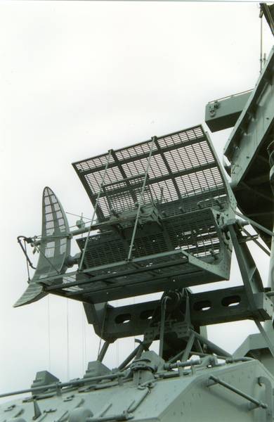
 | 39k | Several radars are visible: the Mk.13 Main Battery Fire Control Radar, 3cm radar within a radome that replaced the earlier Mk.8, the more complex mechanically scanned polyrod array, mounted on top of her large Mk.38 Main Battery Director One with its 26.5 ft stereo (Mk.48) rangefinder. | Photograph courtesy of Pieter Bakels. | |
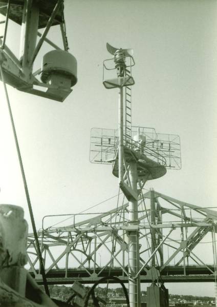
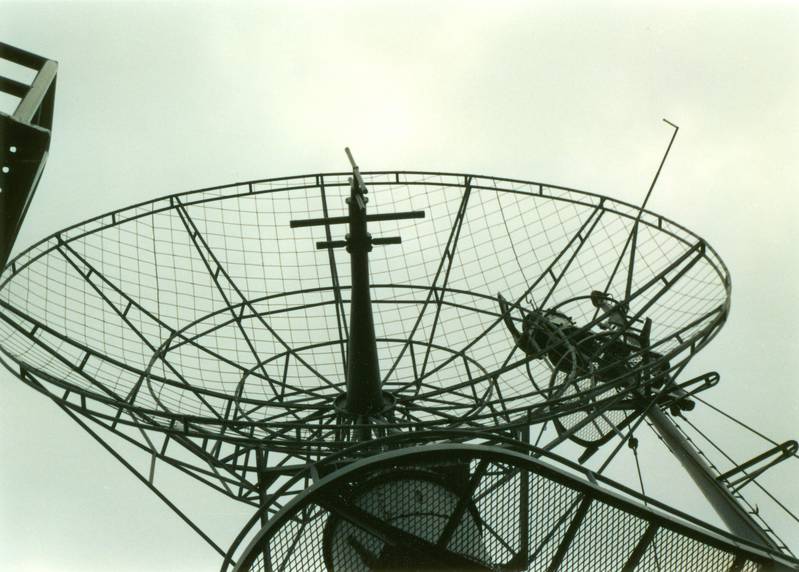 | 69k | Above it, the SK-2, with its 17ft dish antenna for long range radar detection of aircraft. Right behind it, the "SG" surface search radar is visible. Barely visible inside the SK-2 dish, the BM interrogator of the Mk.III IFF system without which controllers would be unable to distinguish friendly from enemy aircraft. | Photograph courtesy of Pieter Bakels. | |
 | 32k | On her maintop "SR", a back-up against failure of the SK-2 with its 15ft x 6ft air search antenna. Mounted on a new mast, a second "SG" surface search radar. In front of her tower, directly above a (now removed 36-Inch searchlight), the back-to-back antenna arrangement of her large TDY jammer, covering both low-and high bands, for force screening which proved very useful in the latter part of WWII against both sea and airborne targets. Behind it on both sides of the fire control tower, another pair (P. /S.) of TDY jammers are visible. On her House Top level, a Mk.12 antenna, mounted on top of a here not visible Mk.37 Secondary Battery Director, which is a replacement for the earlier Mk.4, a fire control radar for the dual purpose, rapid firing, tray loading, 5-Inch/38 Twin Mounts(Mk.28) of the ship. Breech action of this weapon was semi-automatic with power rammers, which permitted loading at any angle of elevation. These mounts had power driven train, elevation and ammunition hoisting, with alternate manual operation. The MK.12 radar proved very successful but ineffective against low-flying aircraft such as Japanese torpedo bombers. A parabolic height-finder, Mk.22 ("Orange Peel"), was therefore mounted alongside (right-hand side) Mk.12. | Photograph courtesy of Pieter Bakels. | |
 | 70k | Visible just under the Mk.12 is the Mk.29 radar dish for use with the GFCS (Gun Fire Control System) Mk.57 (this image and below), a 40mm primary control system. It could also be used to deliver 5-Inch/38Cal. gun orders instead of 40mm gun orders by throwing several ballistic switches in the equipment. Early Mk.57 director installations, lacking a fuze computer and parallax corrector, were used for 40mm gun control only. GFCS Mk.57 used manual tracking and radar range. "Blind" tracking was aided by a "smoothing control", damping the lead angles measured by the computer (Mk.17). In front of the Mk.12/22, a short-range ship-to-ship whip antenna. The small antenna mounted centrally in front of the main antenna was used for Side lobe suppression. | Photograph courtesy of Pieter Bakels. | |
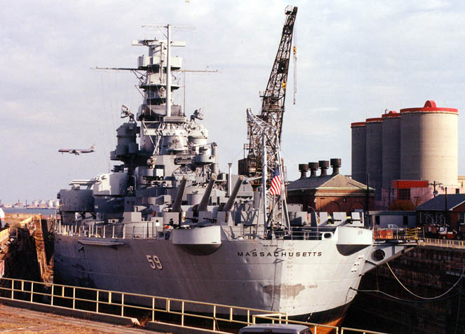
 | 144k | The Massachusetts (BB-59) stretches her sea legs in 1998-99 while enroute to Drydock #3 Boston Naval Ship Yard. | Photograph courtesy of Joe Lombardi, Ocean Technical Services via Ron Reeves (of blessed memory). | |
 | 72k | Stern view, port side. Boston, 1998. | Courtesy of Brian J. Johnson, Franklin, MA. | |
 015910 | 428k | Massachusetts (BB-59) arrives back in Fall River, MA, after a 300 mile trip from the Boston drydock 6 March 1999. Here seen under tow from Boston back to Fall River on 3 March 1999. | Photograph courtesy of Yu Chu. | |
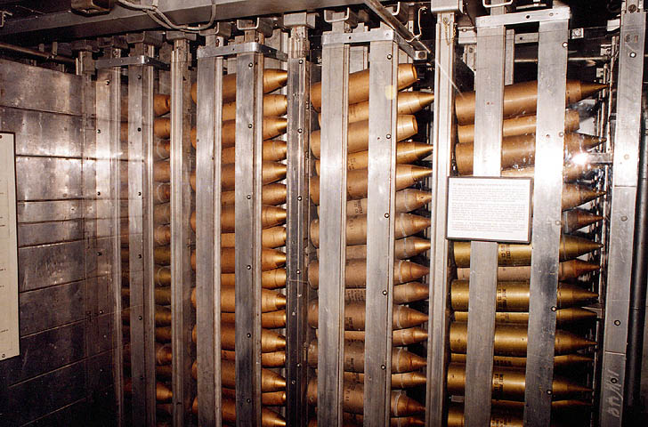 | 107k | Port side ammunition handling room. | Courtesy of Brian J. Johnson, Franklin, MA. | |
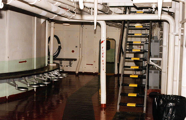 | 93k | Galley area, showing some of the seats around the base of the aft 16" guns. | Courtesy of Brian J. Johnson, Franklin, MA. | |
 | 87k | Get out of jail free card used here. | Courtesy of Brian J. Johnson, Franklin, MA. | |
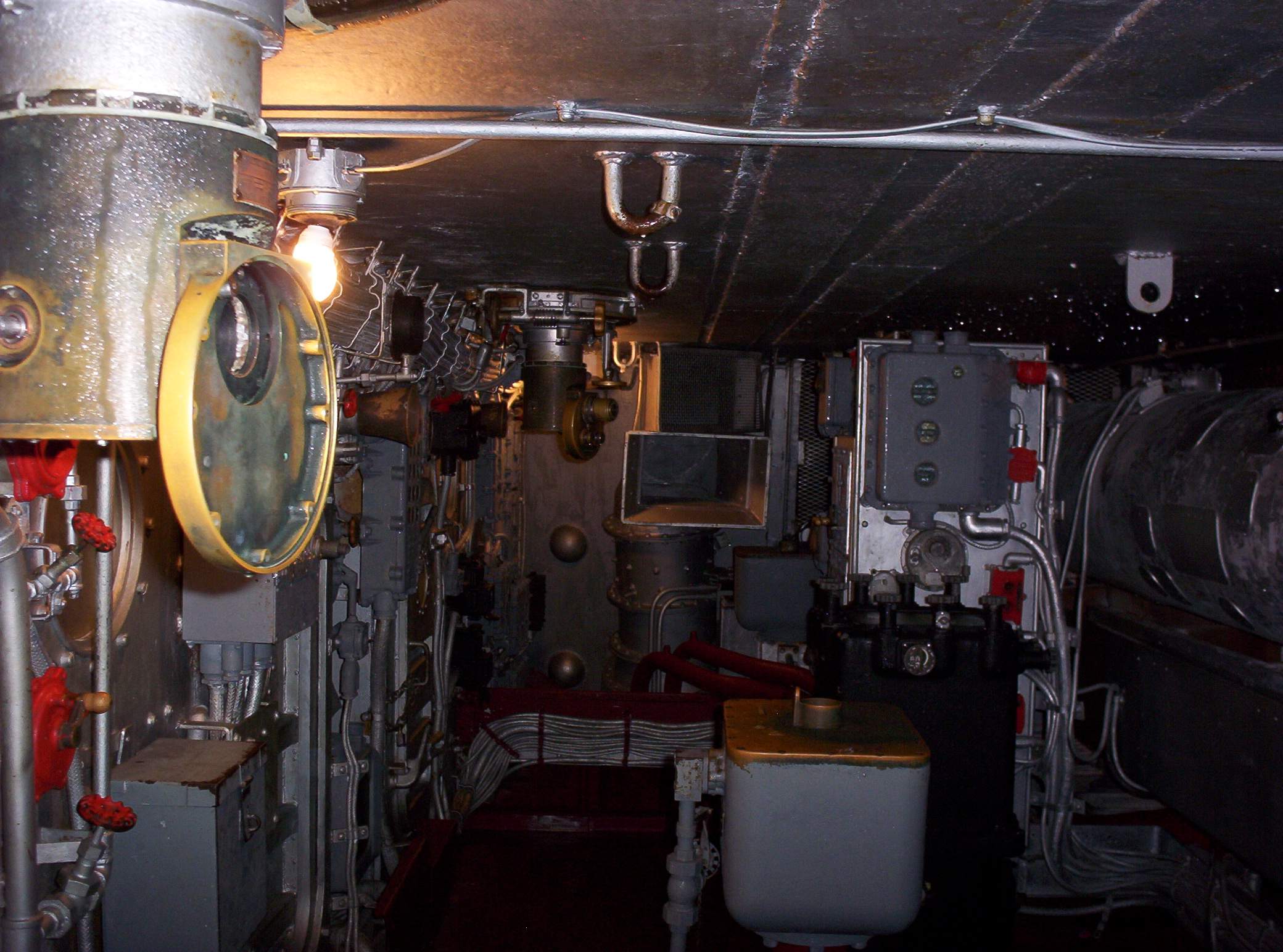
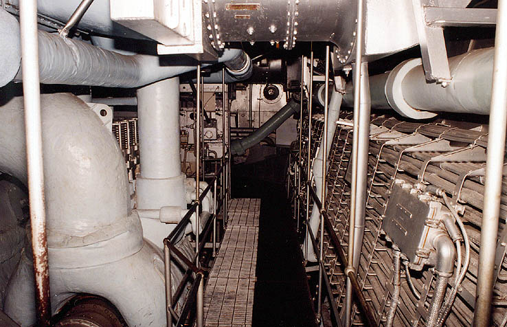 | 110k | The engine room. | Courtesy of Brian J. Johnson, Franklin, MA. | |
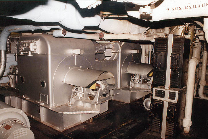 | 93k | Stern turbines, engine room. | Courtesy of Brian J. Johnson, Franklin, MA. | |
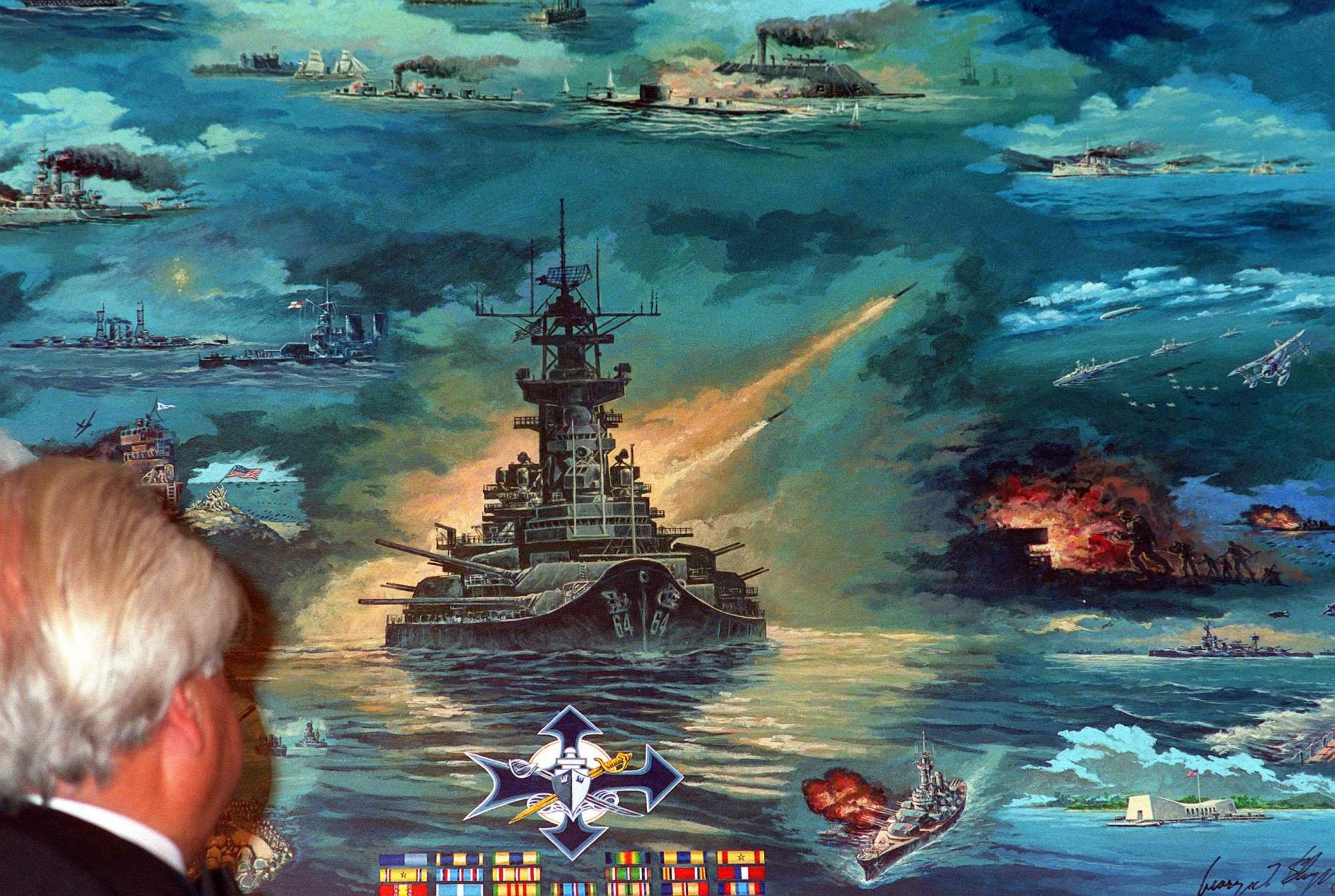 | 376k | A guest studies a painting depicting the history of battleships. The artwork was painted by George Skybeck and presented to the Pearl Harbor Survivors Association during their annual banquet at Honolulu, Hawaii, on 8 December 1991. | USN photo # DN-SC-92-05391, by PHC Carolyn Harris, courtesy of dodmedia.osd.mil, Defense Visual Information Center. | |
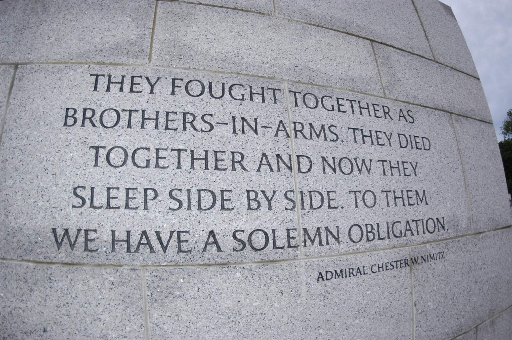 | 371k | A quote made by Fleet Adm. Chester W. Nimitz is inscribed on a granite wall at the National World War II Memorial located on the National Mall in Washington, D.C. Fleet Adm. Nimitz was the United States signatory to the surrender terms aboard the battleship Missouri (BB-63) in Tokyo Bay, Japan on 2 September 1945, thus ending World War II. Established by the American Battle Monuments Commission, the memorial honors all military veterans of World War II, the citizens on the home front, the nation at large, and the high moral purpose and idealism that motivated the nation's call to arms. On 29 May 2004, the memorial was formally dedicated with an estimated 200,000 people expected to attend, and includes 100,000 visiting veterans of all wars. | USN photo # N-0295M-011 by Photographer's Mate 2nd Class Daniel J. McLain, courtesy of news.navy.mil. | |
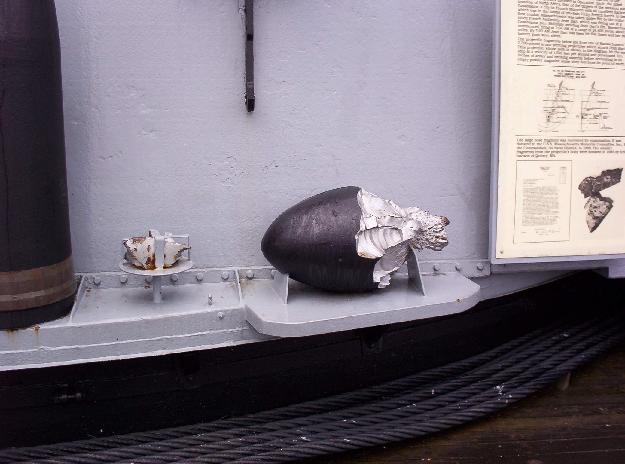 | 258k | A portion of one of the Jean Bart's shells which struck Massachusetts (BB-59) 8 November 1942 on display alongside the #3 turret, December 2005. | Photograph courtesy of Richard Greenleaf. | |
 | 310k | Inside the #3 turret, December 2005. | Photograph courtesy of Richard Greenleaf. | |
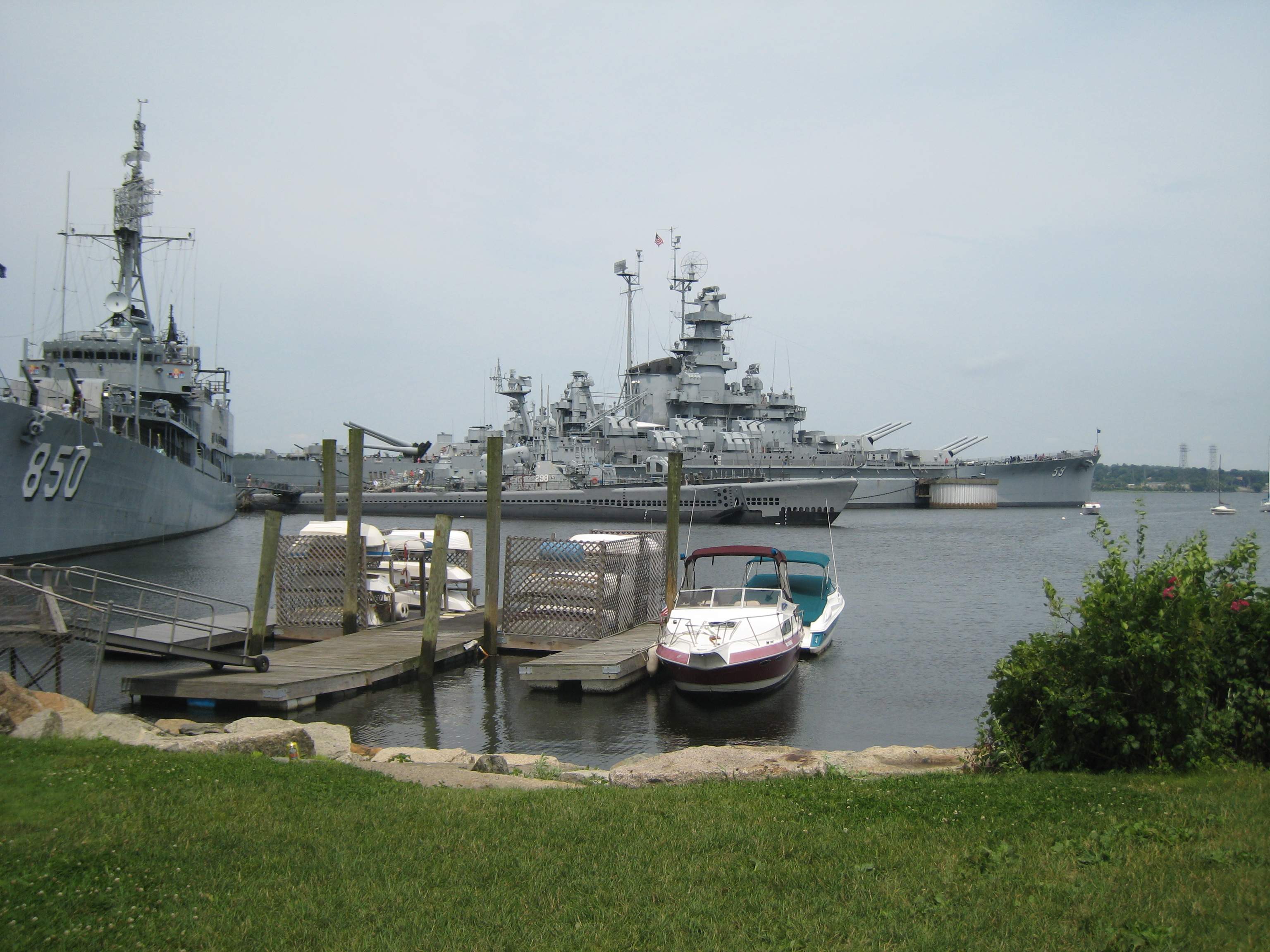 | 583k | View from shore to the Massachusetts (BB-59), Lionfish (SS-298), & Joesph P. Kennedy Jr (DD-850). | Photograph courtesy of John Shane. | |
 | 192k | Communications room aboard the Massachusetts (BB-59), 2009. | Photograph courtesy of John Shane. | |
 | 500k | The names of all men who served on Massachusetts (BB-59) on plaques that go around turret 2. | Photograph courtesy of John Shane. | |
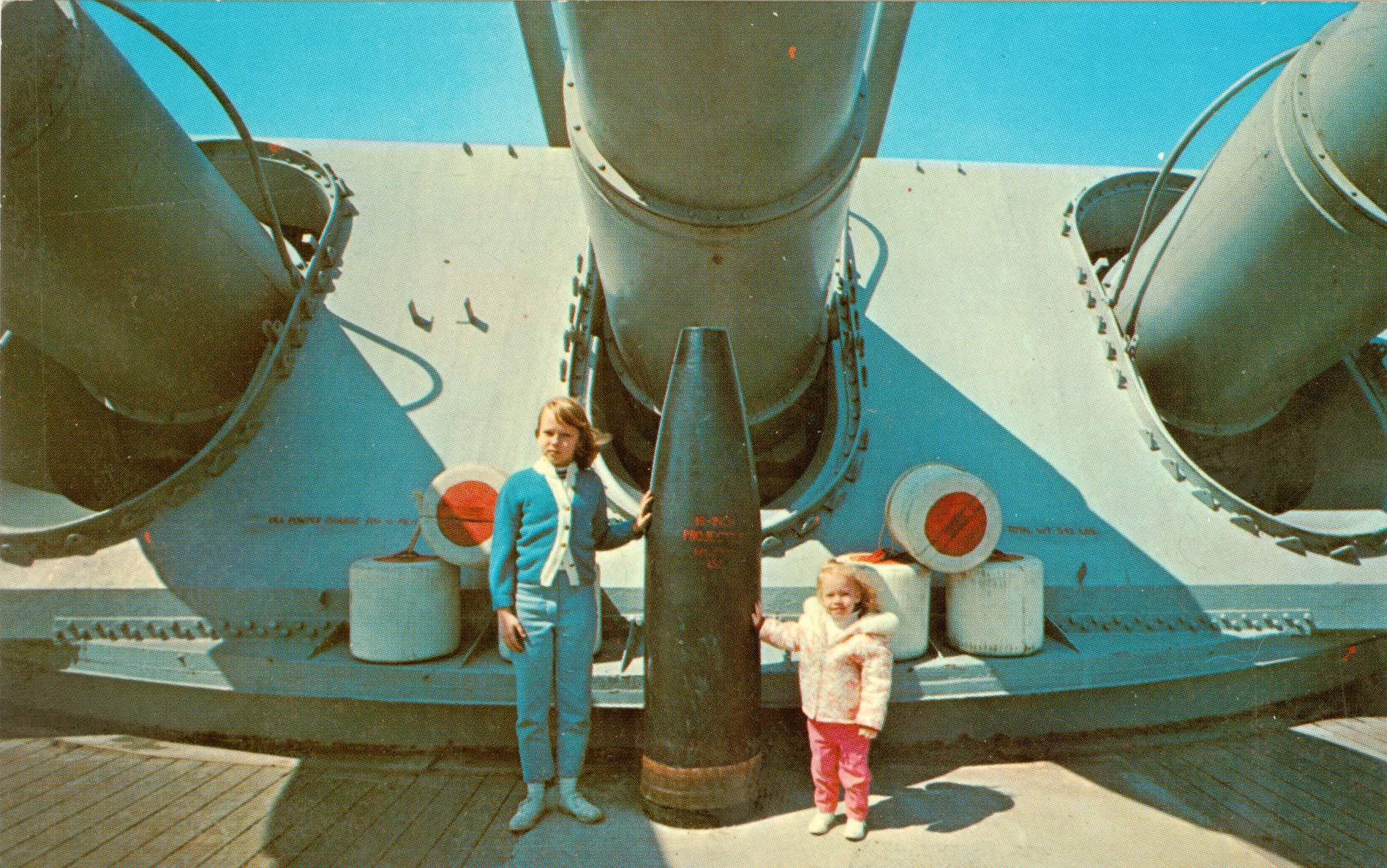
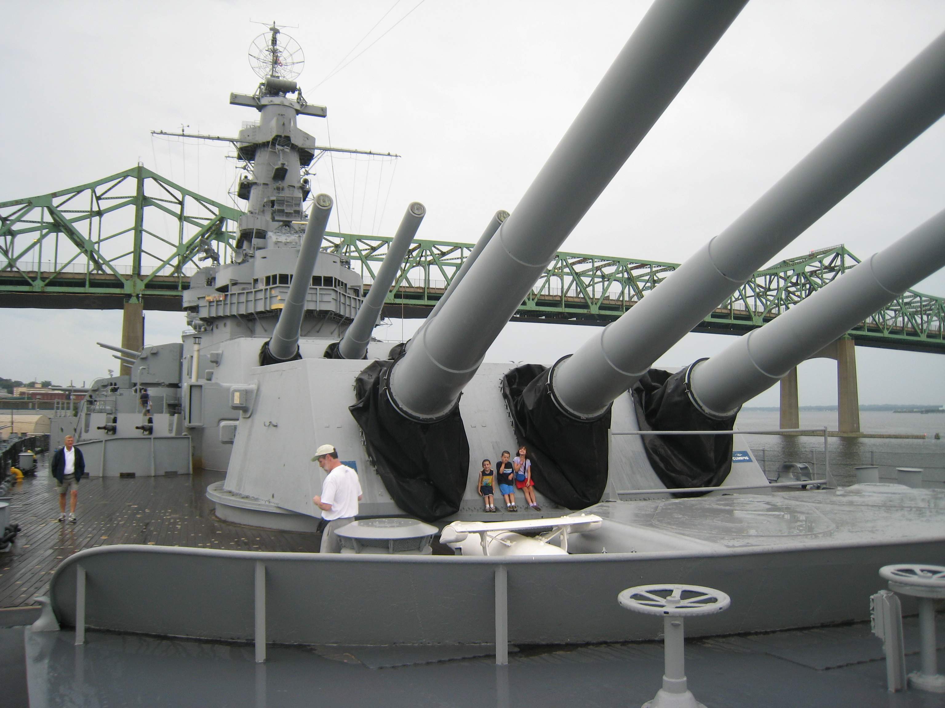 | 428k | Big guns and little people. | Photograph courtesy of John Shane. | |
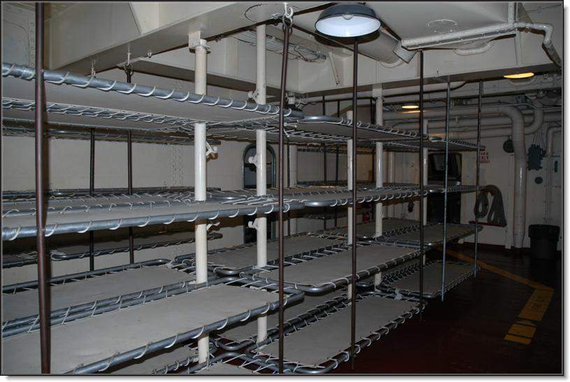 | 70k | Private room for 1(00). | Photograph courtesy of Larry Backus. | |
 | 2.37k | 10 photo PDF of the Massachusetts (BB-59). | PDF courtesy of Pieter Bakels. | |
 | 441k | Turret face of the Massachusetts (BB-59). | Photo courtesy of Pieter Bakels. | |
 | 6.79k | Three photo PDF of Massachusetts (BB-59) in high resolution, 2012. | Photo courtesy of Luo Le. | |
 | 2.52k | Flag Plot of the Massachusetts (BB-59) & 6 other photos in this PDF of Massachusetts, 2015. | Photos courtesy of Jeff Padell. | |
 015977b | 286k | Do you know the names of BB-59's Turret Three's guns? | Photo courtesy of Tommy Trampp via laststandonzombieisland.com | |
| Commanding Officers | ||
| 01 | CAPT. Whiting, Francis Eliot Maynard, USN (USNA 1912) :VADM | 12.05.1942 - 12.12.1942 |
| 02 | CAPT. Glover, Robert Ogden, USN (USNA 1915) :RADM | 12.12.1942 - 27.09.1943 |
| 03 | CAPT. Ruddock Jr., Theodore Davis, USN (USNA 1914) :VADM | 27.09.1943 - 08.04.1944 |
| 04 | CAPT. Warlick, William Walter, USN (USNA 1918) :COMO | 08.04.1944 - 02.05.1945 |
| 05 | CAPT. Redman, John Roland (Jack), USN (USNA 1919) :VADM | 02.05.1945 - 22.01.1946 |
| 06 | CAPT. McLean, Heber Hampton, USN (USNA 1921A) :VADM | 22.01.1946 - 05.08.1946 |
| 07 | CDR. Gimber Jr., Harry Meeker Steward, USN (USNA 1932) | 05.08.1946 - 09.09.1946 |
| 08 | CDR. Carroll, Charles Barrett | 09.09.1946 - 03.01.1947 |
| 09 | LT. Buchan, Marion Lynword | 03.01.1947 - 27.03.1947 |
The contact listed, Was the contact at the time for this ship when located. If another person now is the contact, E-mail me and I will update this entry. These contacts are compiled from various sources over a long period of time and may or may not be correct. Every effort has been made to list the newest contact if more than one contact was found.
| Back To The Main Photo Index | Back To The Battleship Photo Index Page |